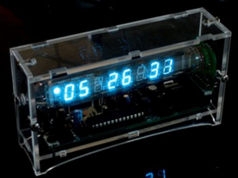
Build the most unique clock on the market, featuring a retro Russian display tube and a clear plastic case so you can appreciate the inner workings of this fantastic gadget!

What will the next generation of Make: look like? We’re inviting you to shape the future by investing in Make:. By becoming an investor, you help decide what’s next. The future of Make: is in your hands. Learn More.

Project Steps

Gather your Materials

Open up the Ice Tube Clock Kit box. Begin by separating the individual components of the kit.

Gather the printed circuit board and the electronic components to be soldered in.

Save the enclosure pieces and the screws for use once the circuit is soldered and ready.

Begin with the DC Jack

The DC Jack is the connector for your external power adapter.

There are three holes for the DC Jack, so place it in the holes and turn the circuit board over. It may be necessary to tape it to the board to make sure it remains in place when you turn the board over to solder.

Be sure that the solder joint is full and strong. You will be pushing the adapter in and out of here, so it is important for it to be sturdy.

Distinguishing Between the Yellow Components

There are three ceramic capacitors, marked with a 104.

There is a 100V capacitor that has a 2.5mm spacing with kinked leads. This must be distinguished from the fuse, which has wider spacing, at 5mm, and a larger yellow head.

Refer to the image to make sure you know which component is which. The component on the far left is the fuse. The component in the middle is one of three 0.1uF electrolytic capacitors, and the one on the right is a 100V capacitor.

Insert the Fuse

In location F1, insert the fuse, which is the yellow component with the 5mm lead spacing.

It is placed next to the jack, but make sure that it sits above the PCB and not flush. This ensures that the fuse has enough room for air to circulate around it.

Clip your Leads!

Clean up the long leads of your components by clipping the leads after you solder them.

Insert Two of the Protection Diodes

Included in the kit are four protection diodes. Gather two of them and insert them in locations D1 and D2.

Be sure that the silver stripe on the diode matches up with the stripe on the silk-screened image on the PCB.

Solder them in, and then clip the leads.

Inserting the 7805 Voltage Regulator

In location IC3, insert the 7805, the 5V regulator.

Bend the legs so that they are at a 90-degree angle.

Lay the component down on the PCB so that it matches up with the outline on the PCB.

To keep it in place, solder one pin on top of the board, then turn it over and solder all three pins.

Clip the leads when they are all soldered in.

Insert the 47uF/25V Electrolytic Capacitor

In location C2, correctly insert the electrolytic capacitor. You can see the specs on the side of the capacitor.

This capacitor is polarized, so insert the longer lead into the hole marked with a “+”.

Solder it in, and clip the leads.

Insert the 220uF/6.3V Electrolytic Capacitor

In location C4, insert the 220uF/6.3V electrolytic capacitor. This capacitor is also polarized so insert the longer lead into the hole marked with the “+”.

Solder it in and then clip the leads.

Insert Two of the 0.1uF Capacitors

In locations C1 and C3, insert the small yellow 0.1uF capacitors (marked with a “104”).

These are the yellow capacitors without the kinked leads. Solder them in and then clip their leads.

It does not matter which direction you insert these capacitors.

Your First Test!

Begin by plugging in your power adapter.

Get a multimeter and set it to measure DC voltages.

Place the black test lead on the grounded silver tab of the 7805 Voltage Regulator. Place the red test lead on the bottom-most pin on the voltage regulator. The meter should read between 7V and 13V.

Now we can check the 5V regulator. Place the black test lead on the same spot as before. Place the red test lead on the top-most regulator pin. The multimeter should read between 4.7V and 5.2V.

If your tests are not showing the proper result, then check to make sure all of your solder joints are nicely soldered.

Unplug your power source before beginning soldering again!

Insert the 270K Resistor

In location R1, insert the 270K resistor (the one with color code red-purple-yellow).

Resistors are not polarized, so you can insert them in any direction. Solder it in and then clip the leads.

Insert the Piezo Beeper

In the location SPK, insert the piezo beeper. It is not polarized so it does not matter which direction you place it in.

This is the alarm! Solder it in and then clip the leads.

Place the IC Socket

The IC Sockets have a notch on one end. Make sure this notch matches up with the notch that is silk-screened onto the PCB.

You can bend a couple of the leads on the socket to make sure it stays in place when you are soldering it. Try to keep it as flush to the PCB as possible.

Carefully solder the pins, being sure not to bridge any solder joints on the socket.

Insert the Chip

The chips don’t fit perfectly into the socket right away, so it is often necessary to bend the pins slightly in order for them to fit into the socket.

Make sure that the end of the chip with a notch is inserted into the side of the socket with the notch. After you double-check this, just press the chip into the socket.

Your Second Test

Just plug in the power adapter and you will hear a beep. If you do not hear a beep, then check to make sure all of your components are soldered correctly and are in the correct locations.

Insert the 100kOhm Resistor

In location R2, insert the resistor with the color code Brown-Black-Yellow.

Solder it in and then clip the leads.

Insert the Remaining 0.1uF Capacitor

The remaining yellow capacitor without kinked leads should be inserted into location C10.

It does not matter which direction you insert the capacitor, so just solder it in and then clip the leads.

Insert the 10K Resistor

In location R5, insert the 10K resistor (color code brown-black-orange). Bend its leads as shown in the image. The gold stripe end should be the lower end of the resistor.

Solder it in and then clip the leads.

Insert the 32.768KHz Clock Crystal

In location Q1, insert the 32.768KHz clock crystal. It does not matter which direction you insert the crystal.

Solder it in and then clip the leads.

Insert the 20pF Capacitors

In locations C8 and C9, insert the 20pF capacitors.

Make sure that you insert the capacitors correctly, and within the small box that outlines the two holes. If you insert them 90 degrees the other way, they won’t work.

Refer to the image, and solder the leads and clip the leads.

Insert the 47uF/25V Capacitor

In location C7, insert the 47uF/25V capacitor.

As with the other electrolytic capacitor, be sure to insert it in the correct direction.

Solder this capacitor in, and then clip the leads.

Insert the High-Voltage Transistor

Two of the pins on the transistor are bridged, so match these up with the bridged image on the silk-screened PCB.

Solder the transistor in, and clip the leads if necessary.

Inserting Another Diode

In location D3, insert another black diode. Make sure that the silver stripe matches up with the stripe on the silk-screened PCB.

Solder it in and then clip the leads.

Insert the large 100V Capacitor

In location C6, insert the large 100V capacitor. Since it is polarized, make sure it is inserted correctly.

Solder it in and then clip the leads.

Insert the Inductor

In location L1, insert the large black inductor.

The inductor is not polarized so it does not matter which direction you put it in.

Solder it in and then clip the leads.

Insert the 60V Zener Diode

In location D5, insert the diode with a black stripe and red-colored body. Make sure that the black stripe matches up with the white stripe on the silk-screened image on the PCB.

Solder it in and then clip the leads.

Testing the Boost Converter

Plug in the board, but do not touch the right-hand side of the PCB.

Place your multimeter on the 60VDC measuring scale.

Touch the black test lead of the multimeter to the large tab of the 7805 regulator. Touch the red lead to the striped end of the diode. You should measure around 60VDC. It is allowed to be between 40-70VDC.

If your measured voltage is 75VDC, then check your power supply in the wall. You may need to use a power supply with a lower voltage rating.

Do not continue if your measured voltage is above 75VDC.

Continuing the Testing

Now unplug the power adapter while keeping the test leads on the same spots.

The measured voltage will drift down slowly, and once it reaches around 15VDC you can safely return to working on the project.

Insert the Remaining 100V Capacitor

The remaining yellow capacitor with the kinked leads and 2.5mm lead spacing should be inserted into location C5.

It is not polarized so it does not matter which direction you place it in. Solder it in and then clip the leads.

Inserting the PLCC Socket

This is a very important step, so make sure you carefully read the instructions.

In the bottom left corner you will see there is a flattened edge in the silkscreen.

When you place the socket, make sure you place it so that the corner that is flattened goes in the bottom left.

Double-check this before you solder! It will be very difficult to fix if it is not placed in correctly!

Insert the 22Ohm Resistor

In location R3, insert the resistor with color code Red-Red-Black.

Solder it in and then clip the leads.

Insert the MOSFET Transistor

In location Q3, insert the transistor with the flat end of the transistor matched with the flat side of the silk-screened image.

Solder it in and then clip the leads.

Insert the 2x10 Female Header

The sockets should be facing up, and make sure that it is flush with the PCB before soldering.

Inserting the Small PCB Headers

Pay close attention to the images and the instructions. You must get this step correct in order to have a properly-fitting clock.

Begin with the slik-screened side of the PCB facing up.

Place the right-angle headers into the PCB as shown in the image.

Make sure that the headers are sitting as flat as possible, and are sturdily attached to the PCB.

Once you know that they have been inserted correctly, solder the headers in.

Make sure that you have everything in this step soldered and placed correctly. It will be very difficult to fix if you move on with the headers incorrectly placed.

Unwrapping the Tube

Carefully unwrap the tube from the packaging.

Begin by finding the wires near the front that are not connected to anything inside of the tube.

Separate these three wires from the rest.

Working with the Tube

Take the three wires that you just separated and thread them through the three holes marked Display NC.

Make sure that the wires are not crossed.

Working with the Tube (cont.)

Thread the remaining wires through so they pass straight through and are not crossed or bent.

Every wire will have a corresponding hole to insert it into.

Working with the Tube (cont.)

Now straighten the wires with pliers, and slide the PCB within a couple of millimeters of the tube.

This process is difficult, and you must take care in working with the wires. Gently pull the bent wires, and carefully slide the PCB down to the base of the tube.

If you find it too difficult you may find that cutting the wires at an angle (i.e. cutting the wires so that the profile looks like “/”) makes things easier. That way you can fit one wire in at a time.

Before you solder the wires, plug the assembly into the main PCB and make any adjustments necessary to make the tube fit straight and secure. When the enclosure is finished, you will be able to make the tube straight at that point as well.
Working with the Tube (cont.)

Bend the wires and then carefully solder each wire.

Once all of the wires are soldered in, you can clip the leads.

Plug in the VFD Chip

There is a flat corner on the MAX6921 chip that must be matched up with the flat corner on the chip’s socket.

Once you have this matched up, press the chip into the socket.

One More Test!

Now plug the tube into the socket on the PCB, turn the lights off, and then plug in the power adapter.

You should see some numbers show up on the display. If the numbers do not show up, check to make sure your soldering is good and the components are inserted correctly; especially the VFD chip.

Wait a few seconds after unplugging the adapter, and then you can move on to finish the soldering.

Installing the Battery Holder

Deposit a small bit of solder on the middle tab of the battery holder.

Place the battery holder into place, and then solder the two leads on the other side of the PCB.

Insert the Final Diode

In location D4, insert the remaining diode with the sliver stripe matched up with the silver stripe on the silk-screened PCB.

Solder it in and then clip the leads.

Insert the Switches

In locations SW1, S1, S2, and S3, insert the switches. The push-button switches are all the same, so it does not matter which one goes where. However, make sure that the slide switch is inserted into SW1.

Make sure that they are all flush with the PCB before you solder them in and move on.

Building the Enclosure

Now that you have finished all of the necessary soldering for the PCB, it is time to build the enclosure and finish the clock!

Gather the laser-cut acrylic pieces, remove their paper backing, and poke out all of the hole bits left over from the laser-cutting process.

Building the Enclosure (Part I)

Carefully place two 4-40 screws into the two small holes on the front plate. This is a symmetrical plate.

Screw the hex nuts on so that they are just below the end of the screw.

Do the same to the other plate. This plate is not symmetrical, so take a look at the image to make sure you have the screws inserted correctly.

Building the Enclosure (Part II)

Next, place two 4-40 screws through the two holes in the PCB from the top side, and fasten them securely with two hex nuts.

Place the PCB on the bottom plate. It will fit only one way. Use two more hex nuts to hold the bottom plate in place.

Building the Enclosure (Part III)

Next, place the back plate onto the assembly and align the holes and enclosure guides.

Flip the two pieces over and place the front on top.

Place the side piece with a hole in it on the side that has the free end of the tube.

The hex nuts will easily slide into the T-slots in the plastic. Do the same for the other side as well.

Building the Enclosure (Part IV)

Set the clock upright and place the remaining two hex nuts into the sides on the top.

Place the top piece and align the hex nuts with the T-slots.

Now tighten down all of the screws, and you will be finished!

Finishing Touches!

Congratulations! You have finished building your Ice Tube clock!

Setting instructions are on the bottom plate of the clock. Plug it in, and enjoy!