[youtube:http://youtu.be/Z0K_tAZyO2g]

Light plays an important role in sleep. Bright lights keep us awake and dim lights help us get to sleep. One of the best tricks for getting to sleep is to start turning off lights before you actually go to bed. By gradually reducing the amount of light, it helps you to more gently and easily fall asleep.

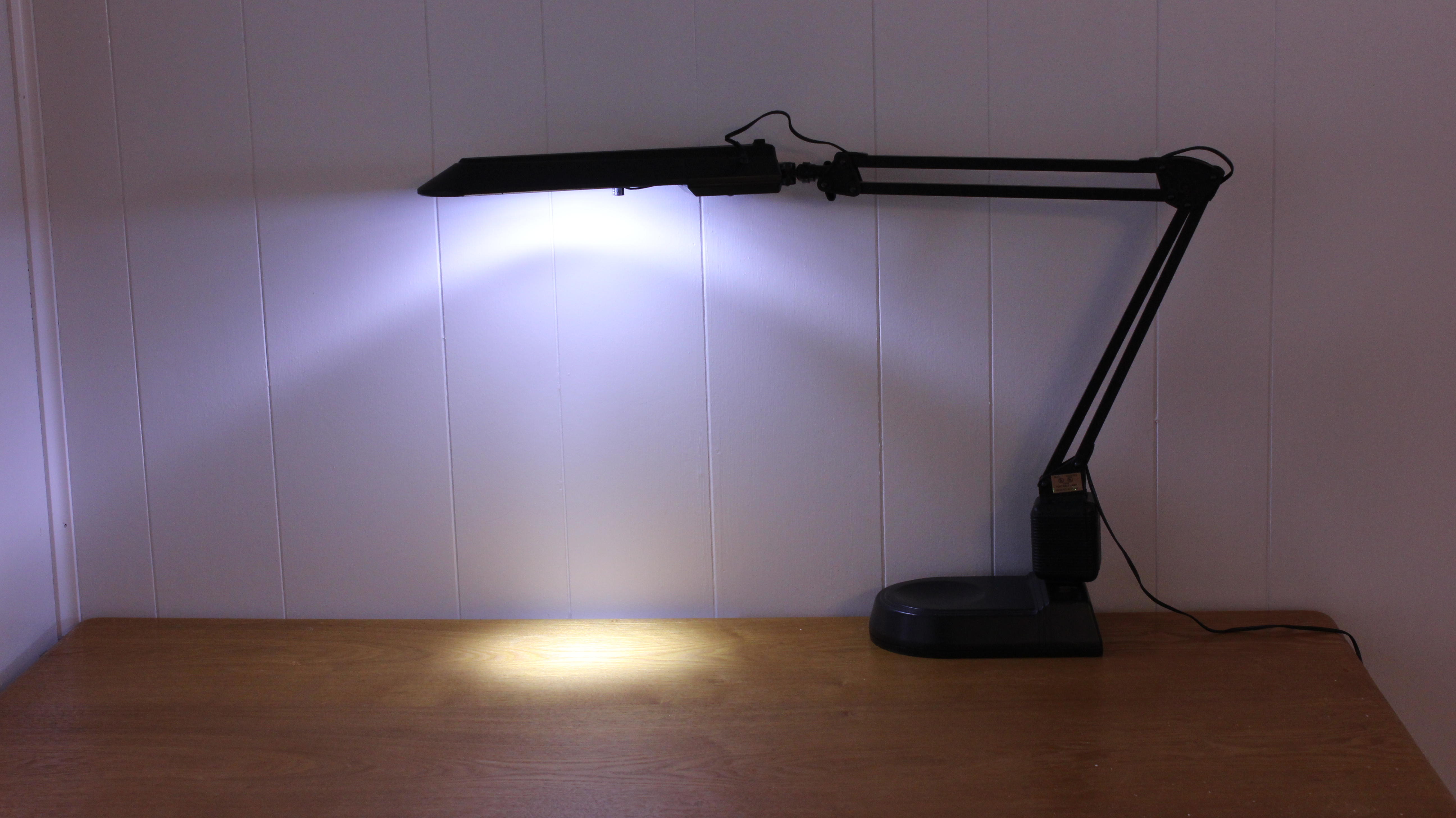
But unfortunately, most lights aren’t dimmable. And it is pretty inconvenient to have to be constantly adjusting the lights. So I designed a simple LED Lamp with a sleep timer that will automatically dim itself over a set amount of time. Here is how to make it.

Main

What will the next generation of Make: look like? We’re inviting you to shape the future by investing in Make:. By becoming an investor, you help decide what’s next. The future of Make: is in your hands. Learn More.

Project Steps

The Circuit

This is the basic circuit that we will use for this project. Here is how it works.

Power for the lamp is provided by a 12 volt DC power supply. The control circuit uses a LM7805 voltage regulator to keep the voltage in this section at a constant 5 volts. A 5k potentiometer (variable resistor) and a 6.8k fixed resistor control the voltage of a 330 microfarad storage capacitor. The potentiometer is also connected to the gate of an IRF510 MOSFET. The voltage at the Gate pin controls the output of the MOSFET and sets the brightness of the LED array. So by adjusting the potentiometer, you can change the voltage of the MOSFET gate pin and change the brightness of the LEDs. This acts as a basic dimmer for the lamp.

The automatic dimming function is activated by opening the switch between the potentiometer and the capacitor. The capacitor is initially at the same voltage as the output of the potentiometer. However, when the switch opened, the capacitor slowly drains through the 10 Mohm resistor. This causes the voltage at the Gate of the MOSFET to drop and the LED array slowly dims over a set time period.

The timing of the automatic dimming is determined by the values of the capacitor and resistor. With the components shown in the schematic, the lamp will be on at full brightness for about six minutes. Then it will gradually dim over the next twenty three minutes. You can also use the potentiometer to set where in the cycle the dimming begins. By using different values, you can change how long it takes the lights to dim. To determine how long the lamp will be on a full brightness, and how long it will take to dim, you can use the following formulas:

Time (full brightness) = R x C x 0.00198 (minutes)

Time (dimming) = R x C x 0.00702 (minutes)

Select a Power Supply

The first thing that you need is a DC power supply (AC to DC power adapter). This will power both the LEDs and the control circuit.

Use a power adapter with an output voltage of at least 5V. It is also helpful if the output voltage of the power supply is a multiple of the LED voltage. For example, if the LED voltage is 3V, then it is easiest to work with a power supply whose output voltage is either 6V, 9V, or 12V. But this isn’t 100% necessary. If the voltage of your power adapter is not a multiple of the LED voltage, then you will need to add a series resistor to each set of LEDs wired in series.

I am using a 12VDC 200mA power supply. But other power supplies can also work. The only difference that it will make is that a power supply with a different output rating will be able to power a different number of LEDs.

Calculate the Number of LEDs To Use

We want the lamp to use about the same amount of power as the circuit that the power supply was originally designed for. So we need to calculate how many LEDs are needed to match the rated output of the power supply.

Start by checking the power requirements of the LEDs. If you don’t know the specifications of the LEDs, you can reasonably assume that each one operates at 3 volts and 20 mA.

Divide the output voltage of the power supply by the voltage of the LED to determine how many LEDs will be wired in series. In this case, 12V / 3V = 4 LEDs in series. Then divide the output current of the power supply by the current rating of the LED to determine how many LEDs will be wired in parallel. In this case, 200 mA / 20 mA = 10 LEDs in parallel. So the lamp will have ten sets of four LEDs in series for a total of 40 LEDs.

If you are using a different power supply, you will end up with a different number but the process will be the same.

Prototype the Circuit on a Breadboard

With any electronics project, it is a good idea to prototype the circuit on a breadboard before soldering it together. This gives you a chance to troubleshoot and correct any errors. Be sure to use the full number of LEDs that we calculated on the previous step. If you use a different number of LEDs, it may changes the output voltage of the power supply. This can cause problems.

If the circuit works like it is supposed to, then you are ready to solder it together.

Solder the Circuit Together on a Circuit Board

After testing the circuit on a breadboard, I soldered the parts onto a perf board. The switch and the potentiometer were not soldered to the board directly; they are mounted to the housing of the lamp and connected with jumper wires.

If you want the wires from the power supply to be routed through the body of the lamp, then you should not solder these wires to the board until after we have finished modifying the lamp.

Remove the Lamp's Power Cord

We will be using the power cord that is attached to the power adapter to supply electricity to the lamp, so we won’t need the lamp’s original power cord. To remove it, just cut the cord near the lamp and pull it out through each section of the stand. If there are any components embedded into the stand, you can either remove them or just cut the cord on both sides.

Remove the Light Bulb and Wires from the Lamp Housing

Now you need to remove the light bulb. Unscrew the housing of the lamp. Then unscrew the light bulb fixture. The last thing that you need to do is disconnect the light fixture from the power cord. In most cases the easiest thing to do is to just cut the wires. You can then unsolder the wires from the switch (if there is one) and finish removing the rest of the wires from the housing.

Route the Wires From the Power Supply Through the Lamp Stand

If you want the new power cord to be routed through the body of he lamp, this is a good time to do that. Starting at the bottom, slide the power cord through the body of the lamp. If you have trouble getting the wires through, you may need to use a stiff wire to help guide them. If the ends of the wires are separated, tape them together while you weaving them through the body of the lamp, otherwise they might get stuck.

Pull the wires out of the top section of the lamp. If you are using an articulated lamp, leave a little bit of slack at each joint so that the lamp can move and bend properly.

Connect the Power Cord and the Switch to the Circuit Board

Feed the power cord into the housing of the lamp head. Then solder the wires to the appropriate place of the circuit board. Also solder the lamp switch to the appropriate place on the board. If your lamp does not have an easily accessible switch, you will need to add one. Any small latching switch will work.

Drill a Hole in the Housing to Attach the Potentiometer

Now we need to mount the potentiometer. Drill a hole that is a little bigger than the threads on the potentiometer. Then insert the potentiometer through the hole and secure it in place with its washer and nut.

Attach the LED Array to the Inside of the Lamp

Now we are ready to attach the LED array to the inside of the lamp. How you do this will depend on the kind of lamp that you are using.

On my lamp there was a metal reflector plate on the inside of the lamp head. I didn’t want to accidentally short any of the connections on this plate, so I added an insulated layer between the circuit board and the reflector plate. I found that the easiest solution for this was to just stick a piece of tape to the back of the circuit board.

To attach the circuit board to the housing, I applied hot glue to the back side and stuck it to the center of the plate.

Reassemble the Housing of the Lamp

With all the parts in place, you are ready to reassemble the lamp. Start by reinstalling any cover plates on the head of the lamp. Then take the power cord and pull any excess back out of the head of the lamp. Leave a little slack in the power cord at each joint and work the rest down to the bottom. Then mount the body of the stand back onto its base.

Use Your Automatic Dimming Lamp

Plug the lamp in and turn it on. You should be able to use the potentiometer to adjust the brightness of the lamp, just like a regular dimming lamp. When you flip the switch on the head of the lamp, the LED will begin to fade. If the lamp is initially at full brightness, it will remain on at this level for six and a half minutes; then it will slowly fade over the next twenty three minutes. By adjusting the potentiometer, you can change where in the cycle the dimming starts.

This system makes a great sleep timer for your lamp. By gradually reducing the amount of light, it can help you to more easily fall asleep. Additionally, a lamp that turns itself off is also a great way to conserve energy if you accidentally leave it on.