The Basic LEDhead is a simple LED – spring contact switch – battery circuit. Other LEDheads will have different circuitry to explore different power sources, flashing rates, etc.

What will the next generation of Make: look like? We’re inviting you to shape the future by investing in Make:. By becoming an investor, you help decide what’s next. The future of Make: is in your hands. Learn More.

Project Steps

What is a LEDhead?

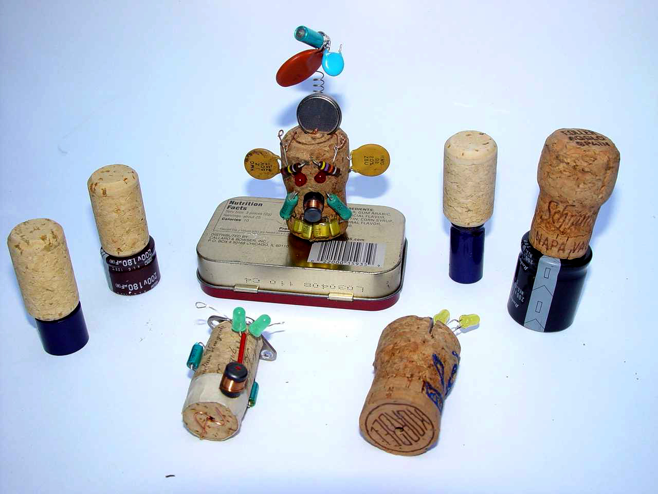
A LEDhead is a simple LED circuit disguised as a cork head similar to a carved tiki head. I use this space (the cork head) for several different electronic circuits. The challenge is getting everything to fit on the cork and work (not short out).

This LEDhead is the basic building block for other LEDheads.

It has a simple battery – switch – LED circuit. The switch is a simple contact switch utilizing a spring or guitar wire.

Once the basic circuit is functioning the LEDhead is further decorated with scrap electronics to create facial features for the LEDhead.

You can decorate in other styles … carving …. glue gun sparklies …. rustic nails … woodburning … acrylic paints … you get the idea.

Parts You Will Need

for each LEDhead: 1 cork, 1 button battery, 1-2 LEDs, 6″ of metal guitar wire or stretchable spring, misc scrap electronics for facial decor.

also needed: small & medium sized paper clips (to act as wires), .24 ga copper wire for wrapping connections and thin wires, heatshrink tubing or electrical tape, pushpin (pokes small holes in cork), and bamboo skewers.

Test Battery & LED(s)

Always check that the battery is charged and your LEDs work. Easy way to do that is just connect the LED to the battery to see if it lights up.

See the LED leads … one is longer than the other – that is the Anode. The Anode goes to positive and the Cathode goes to negative side of the battery. If the leads are the same length look for the little ‘flag’ in the LED … that is the Anode side.

A LED is a light emitting diode. Diodes only let current flow in one direction. That is why the LED will not light up when the leads are reversed on the battery.

Decide on Design Issues

Before you start making the LEDhead you will need to make a few decisions about the style of the LEDhead and how your design will affect your creation process.

Will you hang the LEDhead? Mount it on a bamboo skewer? Glue a magnet at the base? Attach a safety pin for wearing on clothing?

Spring switch or wire switch (or both)? Switch on top or bottom of LEDhead? Lots of blinking (sensitive switch) or less so?

LEDs in eyes or nose (or both)? 1 eye or 2? Blink at same rate or each to its own beat?

Battery exposed or hidden?

Facial features carved or added on with scrap electronic parts?

Those kind of things … each one affects your build process.

Who is making these LEDheads?

Another factor affecting the build is who is making the LEDhead. For young children I usually skip the soldering or just have an adult do it … relying more on a physical connection with wire & heatshrink rather than the solder.

Time may be a factor if this is a group activity so having corks predrilled and wires already soldered onto LEDs and G-Wire is helpful.

Decide on circuit design - In Series or Parallel?

There are a couple of ways to wire up your LEDhead depending on the number of LEDS you are using. For a single LED the circuit is fairly simple.

If you have two or more LEDs you have to decide if you are wiring them up in series or in a parallel circuit.

LEDs in series are wired inline so that the + of one LED will connect to the – of the next. The more LED added in series, the more Voltage needed to power them (but current (amps) stays same). If one fails, they all fail.

LEDs in parallel are wired so that all the + are connected and all the – are connected … these are then connected to the battery. The more LEDs in parallel, the more current needed (but voltage stays the same). If one fails, others stay lit.

The Paper Drill !!

What really makes this project easy is my Spinnit Paper Drill. Designed to drill through reams of paper for a printing / publishing shop. This was a freebie off Craigslist and it has proved itself to be gold.

I use this drill for my cork drilling and book altering drilling. Makes nice smooth holes in soft material. If I don’t have this I use a Dremel for the cork holes. I have not used a regular drill bit and drill press yet for altering corks.

The bits are basically hollow tubes with a good sharp edge. Could probably fashion a hand tool out of a metal tube (ink pen casing?) if we tried.

I use small diameter for spring switch holes (top or bottom), bamboo skewer holes on bottom, holes for wiring, etc.

A larger bit is used for the LED holes and does not go deep.

Put Holes in Their Heads!

Before using the paper drill I press the bit into a block of wax to clean & lubricate the bit.

I also use a soft book underneath so the drill bit does not dull itself hitting wood.

2 size holes are needed here. The small drill (1/8″?) is for shallow 1/2″ deep holes for switch posts, skewer holes, and hanging ribbons. The small also goes entirely through the cork for the eye hole (or nose) to allow the LED leads wiring.

The larger drill (1/4″) is to drill a shallow recess hole (1/4″ deep) for the LED to slide into. If you want your LED to be fully exposed you do not need the larger hole.

After drilling you may need to pick the core bits out of the hole with a stiff paper clip or dental pick. The synthetic corks they make today are fairly stubborn to remove excess.

Drill the holes you need for this design.
LED / Wire Unit: Assemble, Solder & Protect

Okay the LEDs for this project are going into the eyes and only need to have one lead (the positive side) of the LED attached and soldered to a paper clip wire. The other short lead will be going outside the front of the eye socket to connect with the switch on top. If you dont want ‘antennae’ then make both leads longer and route both through eyes to back of head.

If you are creating a nose you need to make both LED leads long by attaching / soldering on the paper clip wires.

Wire wrap or crimp connect the paper clip wire to the LED lead. Soldering recommended.

Both styles will need at least one lead heatshrinked / taped to protect from shorting out the LED on itself.

LED / Wire Unit: More examples

For some projects it is easier to solder and route a smaller .24 ga copper wire to the LED lead than to use the paper clip wire.

We are using the paper clip wire soldered onto the LED so that we can route it around the outside of the LEDhead and use part of it for the Contact Post that the guitar wire uses to close the circuit & light up LED.

If you do not use a paper clip wire on your LEDs (using a .24 ga copper wire instead) you will need to make a contact post … those steps follow the steps for the Guitar Wire part of the switch.

Guitar Wire Switch: Metal to Metal

Time to make the first part of your Guitar Wire (G-Wire) switch. You should make several at a time so they are ready to go for a batch of LEDheads.

Take a small paper clip and straighten it out with needle nose pliers or equiv … nice and straight. Then bend about 1/2 inch of the end of the clip over to create a small 90 degree angle … this becomes the part you stick into the LEDhead.

You can also use copper wire instead of a paper clip but the paper clip has a function later so make at least one with a paper clip.

Wire wrap the ends or secure in copper foil / tubing before soldering. Here you can see a few ready to go … some with paper clips some with wire.

Guitar Wire Switch: Soldering & Heatshrink

Time to solder and heatshrink the G-wire switch. You can skip the soldering (for young ‘uns & such) if you wirewrap or crimp the wire in a electrical connector or small copper tube. Solder if you can …

After soldering or wirewrap/crimp you should heatshrink or electrical tape around the connection. This helps hold together as well as protects from shorts when you push into cork head.

Guitar Wire Switch: Contact Post

If you are using just .24 ga copper wire on your LEDs (not paper clip wire) than you will need to make a Contact Post for your LEDhead.

The Guitar Wire Switch has to connect with something to make a complete circuit so we will create a Contact Post that is mounted around the G-Wire.

Solder & heatshrink the contact post.

Guitar Wire Switch: Spring into Action

Another form of a Contact Post is the Stretched Spring variety. This will have the G-Wire switch mounted inside the spring coil so it connects the circuit that way. This is a sensitive type of switch and needs adjustment once made.

Here you see the stretched spring already wirewrapped to a copper wire (or paper clip wire). Solder this connection.

LEDhead Eyes: Insert 1st LED eye

Now that your LED leads are soldered and protected you can insert the 1st one into the cork head.

Insert the insulated lead through the head but route the second lead out the front of the corkhead …. in other words – do not put the second lead through the cork.

Adjust depth of LED in eye socket.

LEDhead Eyes: Insert 2nd LED eye

Time to add the second LED eye. This eye does not need the heatshrink on it because the first eye already is insulated against contact.

Also – This LED only needs 1 lead to be soldered to the paper clip wire because the second LED lead will go out front of corkhead and connect with the 1st LED eye’s wire lead.

Insert LED through cork to back of head. It may get a bit snug since it is trying to work itself around the 1st LED eye.

Adjust depth of LED in eye socket to your preference.

LEDhead Eyes: Connect Front LED leads

Once you have both eyes in you can connect the 2 leads together. Be sure you the correct two together. They both should be your negative (cathode) leads.

This connection is going to the G-Wire part of your switch

Insert wisdom here.

Insert wisdom here.

Insert wisdom here.

Insert wisdom here.

Insert wisdom here.

LEDhead Switch: Add G-Wire to head

Time to insert the Guitar Wire (G-Wire) unit into the head. If it does not fit snug you may want to add some wood toothpick piece or matchstick to fill in the gap … or hot glue.

The wire attached to this G-Wire will go to the battery (positive + side) to complete the circuit.

Insert wisdom here.

Insert wisdom here.

Connect Battery & Test Circuit

more info …

Mount Battery

more info …

Insert wisdom here.