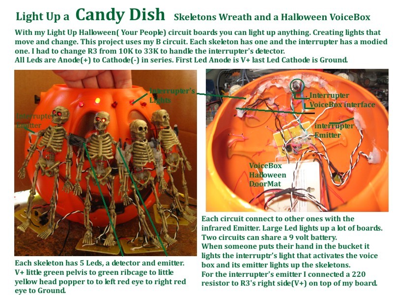
You can use my Light Up Halloween B circuit board to light up a candy dish or anything you desire. This one is for Halloween with a skeleton wreath and a pumpkin bucket for the dish. In this circuit I am using what I call an interrupter. It has both the infrared detector and emitter in one package. This one faces straight up and has four leads. See the pictures. In this B circuit board I needed to change R3 from 10K to 33K to handle the interrupter. I haven’t modified the C & D circuits to use the interrupter yet. Also, because the interrupter has its own emitter I just put a 220 ohm resistor on the board next to R3 to power it. The right side of R3 is V+ (9v). You just solder the 220 to R3 on top of my board.
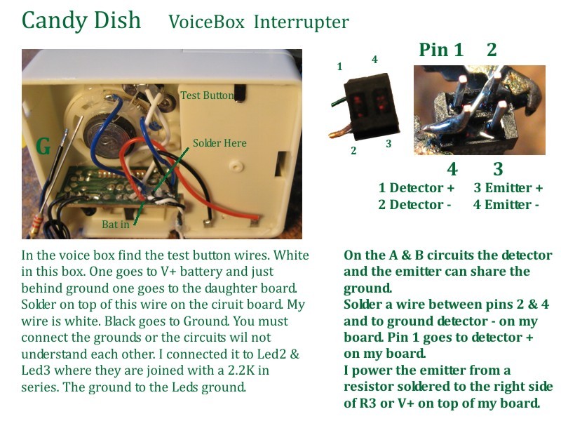
The interrupter has four leads so just solder wires to the outside corners of each lead. The emitter and the detector can share the ground in the A & B circuits. The detector is reversed on the C & D circuits. One small wire or lead trimming can be used to connect pins 2 & 4 on the interrupter. Interrupter Pin 1 is Detector Collector (+), 2 is Detector Emitter (-), 3 is Emitter Anode (+), 4 is Emitter Cathode (-). Just three wires are needed for the A & B circuits boards. Ground to detector (-) on my board. Interrupter collector (+) to detector (+) on my board. Interrupter emitter (+) to the 220 resistor to V+ next to R3.
The interrupter sometimes called a PhotoReFlector come clear or tinted to help with ambient light. Here are some current parts and where to get them. Jameco.com OPB606A(same as mine) Part no. 1872628, Solarbotics.com Line Sensor QRD1114 clear square, OPB730F IR Darlington Photoreflector tinted red round. They all work about the same. Why I call them interrupter is where you find them being used. Your printer has one that tells the printer where the paper is. That is why clear printer sheets have a white stripe label on the top edge. In hobby robots they are used for line tracking and object sensing.
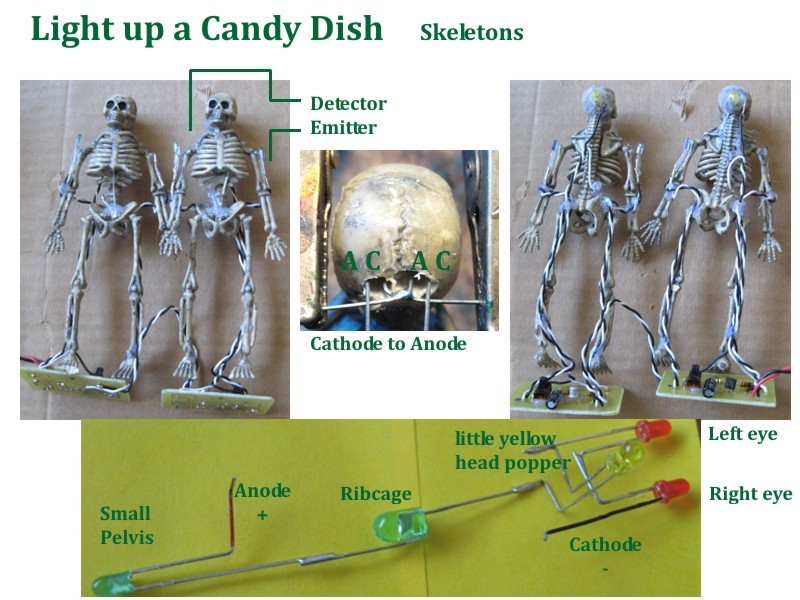
Each skeleton has my B circuit board with emitter and detector and 5 LEDs. I drilled a hole through each eye all of the way through the skull just a bit too small for the LEDs. From the back of the skull I drilled those holes out to fit the LEDs easily, but not all the way through. This stops the LEDs at a good spot. Glue them in place. Two small red LEDs for the eyes. A small yellow LED behind the head to pop it off the background. One normal-sized green LED inside the ribcage. One small green LED inside the pelvis. All of the LEDs are connected cathode to anode. V+ to the anode of little green pelvis LED, to green ribcage to little yellow back of head to left red eye to right red eye, and from that cathode to ground. The detector is on the right shoulder and the transmitter is on the left shoulder. Glue them on with enough wire to aim them once they are installed.
In this project I use a B circuit to run the interrupter and the emitter is used to light up the skeletons. Aim the emitter at the first skeleton’s detector. Turn on the transmitters and all the skeletons light up. Turn off just the B interrupter circuit’s transmitter and the lights go out. By combining other circuits you can create motion art. Just aim the emitters at the detectors and the lights move.
A normal-sized LED emitter can light up a big area and many of my circuits at one time. The side shooter two-lead types have a very narrow beam and only go about three inches. In this set up I can light up the next skeleton easily. Shielding stray infrared is a good idea, but stray infrared can also be fun.
In the A & B circuits the lights come on when the detector is lit up by an emitter. In the C & D circuits the lights go out when the detector is lit up. In the A & D circuits the switch is connected to V+ to turn on the emitter. B & C circuits have the switch connected to the transistor so the emitter only turns on if the detector is lit and the transistor is on. Many wonderful things can be made with my circuits.
I found a Halloween voice-box doormat at my RiteAid in Hollywood and I interfaced it with my circuit using the LEDs as a voltage divider to the test button. On the voice box’s circuit board find the test switch that has two wires. One wire goes to to V+ (3 volts) and the other is next to the ground contact going to the daughter board. Solder your wire on top of this wire. Whenever you interface between circuits you must connect the grounds or they will not understand each other. Always put a resistor in series with your connection. My circuit runs on 9 volts and the voice box uses 3 volts. I used the point between LED 2 & LED 3 and 2.2K resistor in series.
With my circuits you can use a switch to short the detector to turn on the transistor. Connect one wire to the detector’s “+” lead and the other to the detector’s “-” lead. I put a switch by the first skeleton and when it is on all of the skeletons light up.


