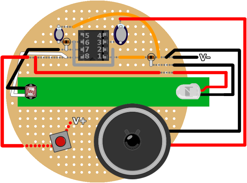
The LDR Synth is a light-to-sound noisemaker built with relatively common components. As the name would imply this project uses a Light-Dependent Resistor – LDR, commonly referred to as a photoresistor – in combination with the venerable 555 timer to produce rapid pulses that output as a pitch range through an 8Ω mini speaker.
The 555 itself is a tiny integrated circuit – IC – that looks like a little bug. It’s assembled in this 8-pin dual in-line package configuration:
Believe it or not that little guy can be found in everything from modern toys to yesteryear’s windshield wipers. Even today it is estimated a billion of these ICs are manufactured annually.
You can read up on the theory, background, and fundamentals of the 555 timer in Charles Platt’s Make: Electronics book, pp. 150–161, available from the Maker Shed or from your local RadioShack store. Additional links to resources I commonly scour for knowledge of the 555 timer and projects built with it are available at the end of this project guide.
We’ll be operating the 555 timer in astable mode, which basically means it emits one pulse at a time. Take a look at the simplified diagram below to see what is going on inside the 555 timer as it relates to this circuit:

As noted the astable 555 will emit pulses. The duration of that pulse, or rather the space between pulses, is typically determined by the values of a resistor between pins 7 & 8 that connects to VCC, and a capacitor between pin 6 and GND. While this is essentially true with this circuit (see schematic below), the value of that resistor (the photoresistor) will vary in relation to the amount of light being shined upon it. Thus when there is less light, there is more resistance, and the duration between the pulses increases, emitting a deeper pitch tone. When there is more light, there is less resistance, and the duration between pulses decreases, emitting a higher pitch tone.
Here’s the circuit schematic:

The capacitor between pin 6 and GND also controls the timing of the pulses emitted by the 555. In the schematic above I’ve listed a 2.2μF electrolytic capacitor, but you can adjust the value of this component. Thus I highly recommend you breadboard your circuit first, so you can experiment with the LDR and the value of this capacitor. Your layout should look something like this:

Changing the capacitor on the top side of this breadboard layout produces the following audible results. Because the amount of light hitting the LDR was quite low, in a controlled, dark setting, the sounds you hear are emitted as clicks. This will not be the case when the light from the LED is shined upon the LDR, as you’ll hear later.
2.2μF:
4.7μF:
6.7μF:
So you can imagine even with a high-brightness LED, the 6.7μF capacitor will produce a deeper tone than the 2.2μF. In my experiments I found that anything outside of those ranges was either too high-pitched to be tolerable or too slow to be substantial. But play around with the setup and choose the configuration that works for you. I eventually opted for the 2.2μF capacitor given the brightness of my LED and the light properties of the material I chose for the tube.
I sourced this green tube from a 99¢ store. It was the shaft of a bouquet of synthetic flowers. The armature holding one of the flower’s stems was also sourced for the metal rod used to slide the LED in and out of the tube like so:
Which at full brightness produces a sliding range of sounds like this:
And like that we can turn light into sound!
Watch the following video to get another snapshot of how it all comes together, and follow the steps below to build your own LDR Synth. I’ve included some notes in the conclusion about further modifying this project, and I’d like to see any ideas you come up with.
| This project is inspired by the 555 Slider Synth by Dino Segovis. I am indebted to Dino for this and other Hack A Week projects and ideas. |


