Nothing says “machine” quite like a bunch of gears turning in time with each other. It’s an iconic image. Unfortunately, gears are expensive and hard to find pre-made. You can scavenge them from discarded machines, but the selection is limited, and it’s possible to amass a whole drawer of gears without having any two that actually fit together.

When I began making kinetic sculpture, this was one of my major dilemmas. So I developed an easy and relatively fast technique for making my own gears out of metal plate that also has the advantage of giving them an inviting, toy-like appearance.

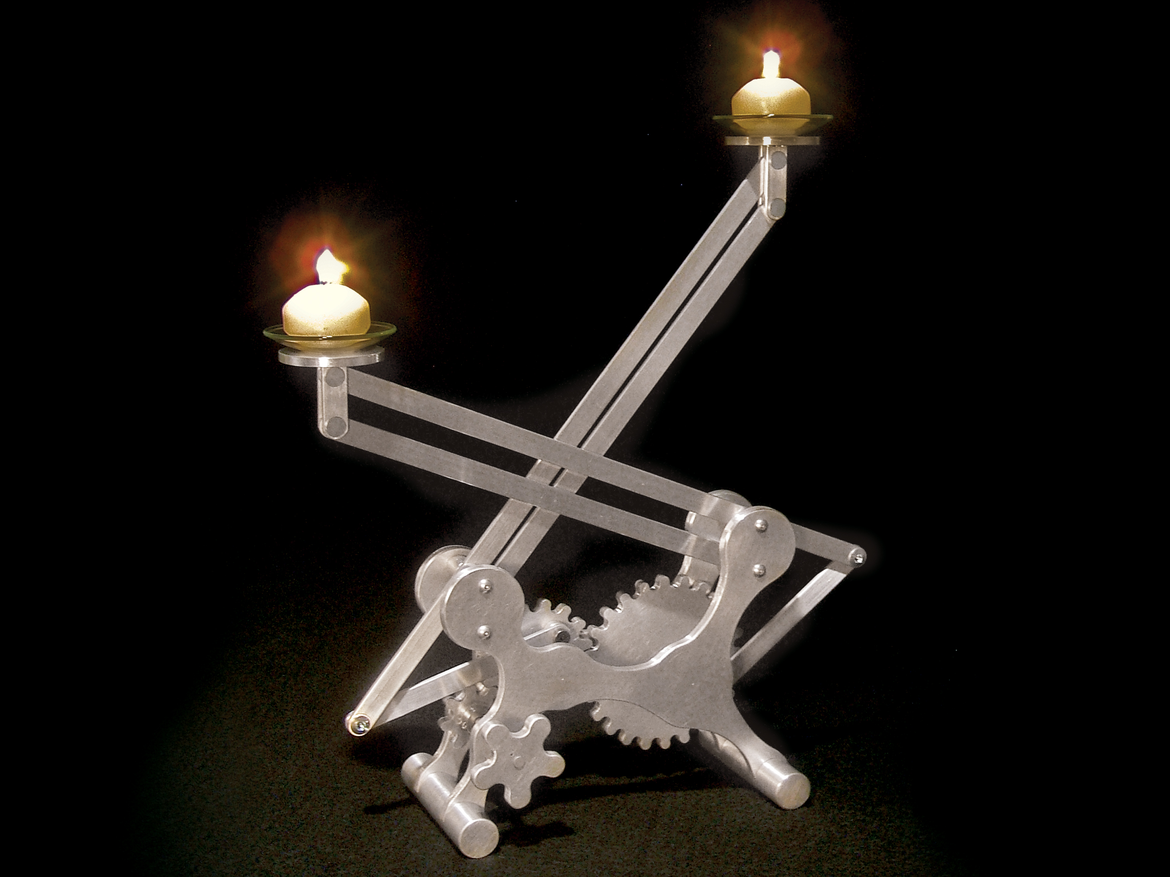
Here’s an elegant, all-aluminum candleholder with a movement containing 3 handmade gears. The drive gear or pinion on the left pushes 2 candle-bearing arms up and down on either side, and because of the different sizes of the gears, the candles move at different rates.

An 8-tooth drive gear or pinion gear turns 15- and 24-tooth driven gears, each of which moves a different arm. The 2 driven gears have a gearing ratio of 5:8, so the 2 candleholders reach the same relative position, such as maximum height, with every 8 revolutions of the smaller gear or every 5 of the larger one. Either way, it takes 120 teeth for an arm to transit its full range of motion, which corresponds to 15 full turns of the drive gear knob.

Movable parallel arms hold the candles, using the same principle as the classic Luxo L-1 desk lamp: the 4-bar, parallelogram linkage. On each arm, the lower pair of pivot points and the upper pair of candleholder anchor points are both vertical and 1” apart, and it’s this relationship that keeps the candle cups level in any arm position.

The gears move the parallel arms by means of a connecting arm, a simple crank linkage that converts rotary motion to reciprocating (back and forth) motion.

What will the next generation of Make: look like? We’re inviting you to shape the future by investing in Make:. By becoming an investor, you help decide what’s next. The future of Make: is in your hands. Learn More.

Project Steps

Mark the gears.

The gears are made by drilling holes around a circle, and then cutting material away so that the spaces between the holes become the teeth.

Download patterns for the gears and all other project parts from the Documents section above. To calculate the radius of each gear’s pitch circle, which runs through the center of the teeth, I used the formula: r = s * n where s is the tooth size and n is the number of teeth. I used a 1/4” drill, giving a 1/4” tooth size, so for my 8-, 15-, and 24-tooth gears, I got pitch radii of 0.637”, 1.194”, and 1.910”, respectively.

Center-punch the center of each gear on the 1/4” aluminum plate and use a protractor and scribe to mark the angle position of each tooth gap. The 8-tooth gear needs a mark every 45∘, the 15-tooth gear every 24∘, and the 24-tooth gear every 15∘.

For each gear, use a straightedge to scribe lines radiating from the center out to the angle marks. Set a drafting divider to the pitch radius (I did this with a caliper) and scribe the pitch circle. Similarly mark the outer circles. On the 2 larger gears, mark lines to position the connecting arm holes, at 0.687” radius for the 15-tooth gear and 1.125” for the 24-tooth.

Punch, drill, and cut.

Wherever the pitch circle crosses the radiating lines, punch and drill a 1/4” hole. Also drill the center with the 1/4” bit. The connecting arm holes need to be tapped for 10-24 threads,so punch then drill these with a #25 drill bit.

Cut the gear out as much as you can on a band saw.

CAUTION: Aluminum dust is very harmful. Wear a respirator and work in a well-ventilated space.

Finish the teeth by filing them until they are semicircular and even-looking.

Test and tap the gears.

Test-mount the gears onto a wood board using 1/4” bolts or rod. Leave a tiny bit of room, or “slop”, between the gears to decrease the chance of binding. Turn them, and mark any problem areas for more filing.

To tap the holes for the connecting arms, clamp the gear so the hole location is off the edge of a table. Secure the 10-24 tap into the handle, put a couple drops of tapping oil on the tap, and screw it slowly into the hole. Apply light pressure, and turn back every quarter turn to break off the curls of metal. Go all the way through the hole before backing the tap out. Clean the hole, and screw in one of the 10-24 shoulder bolts to test the threads.

Mark the body.

These gears are not precise, so you need to lay them out and adjust their relative distances before you machine the body pieces that they mount to. However, the distances to the arm pivot points are fixed and must be accurate. Follow the vertical and diagonal measurements on the pattern at makezine.com/21/candleholder, and within these constraints tweak the gears’ relative horizontal positions so that they mesh effectively. Center-punch your marks, but hold off on drilling yet.

Tip: Use a combination square and a divider to mark vertical lines and distances from the bottom edge of the plate.

Follow the pattern to outline the body. Use your center marks to create the outline, scribing circles and connecting them with “necks”. I used an oval drafting template to make smooth curves.

For the 2 feet, mark two 7/8”-diameter half-circles at the bottom. In the upper corners, mark 7/8”-radiuscircles (1-3/4” diameter) that encompass both arm pivot holes. Make the central circles small enough to show off the mechanism inside. The resulting outline will be fun and reminiscent of old machines.

Cut out the body.

Roughly cut the back panel of the body on a band saw and drill the holes. The 11/64” holes in the corners are for 8-32 machine screws that hold 1-1/2” threaded standoffs between the 2 panels.

Use the back panel as a template to mark the front panel. To improve visibility of the gears, make the middle area of the front panel a little smaller. Clamp the panels together and redrill the 1/4” holes for the pinion (the smallest gear) and the 11/64” arm holes through the back and front panel together. These are the only holes in the front panel.

Tap the holes for the larger gears on the back panel the same way you tapped the gears in Step 3.

For the pinion axle, which will connect to the knob, cut a 1” piece of 1/4” steel rod. Put one end through the center of the pinion and slip a clamp-on shaft collar on top. To join the collar and pinion, drill a 1/16” hole down through both, off to one side, and use a small hammer to drive in a 1/16” tension pin.

Mark the knob and feet.

Make the knob the same way you made the gears, as a 5-tooth gear with 1/2” teeth (pitch radius = 0.796”, marks every 72°). Drill and attach the knob to a shaft collar with a tension pin, the way you did the pinion above.

For the feet, cut two 4” lengths of 7/8” aluminum rod. They need 2 slots cut halfway through them, 1/4” wide and 1-1/2” apart. Put the feet in a vise and use a hacksaw to cut each side of the slot, and then saw diagonally across both to clear out material in between. Finish clearing out the slots with a coarse file until the body panels fit in them. You’ll attach these feet with epoxy later.

Cut the arms.

Each of the larger gears drives an arm that moves 2 parallel levers up and down. The other ends of these levers hold the candle bracket, forming a 4-bar parallelogram linkage that keeps the candle upright. All the holes need to be placed accurately for the movement to work.

Cut the arms. Refer to the connecting arms pattern under Documents. All measurements are based on the centers of the holes, so add some extra length for the ends, and grind or file the corners round.

Drill the holes. Some need to be 1/4” while others are 13/64”. The connecting arms attach to the gears with 1/4”-diameter shoulder bolts and the parallel arms pivot on 1/4” threaded standoffs. The arm parts attach to each other and to the candle brackets using 13/64” binding posts.

Cut the spacers. Ten spacers of varying lengths hold the arms and gears at the correct distances between the front and back panels. Referring to the spacer plan online, cut the 2” unthreaded aluminum spacers down to the lengths needed with a hacksaw. Cut them a bit long and then file them down to a hair short, to allow for free movement.

Make the candle brackets.

Cut two 2”-diameter discs out of the thinner (1/8” or 3/16”) aluminum plate. Drill four 9/64” holes in each, following the bracket pattern online.

Cut four 2” lengths of the 1/2” x 1/8” aluminum bar, round the bottom corners, and cut and drill per the pattern. Each short length of bar needs 2 posts cut out of the top to fit into the holes in the disks. Use a file to round the corners of each post, and insert the bars into the disks.

To fully test-assemble the brackets, I cut and drilled an extra bar to sit in between the others, then secured them together with the 3/8” binding posts. The posts should be snug and stick out about 1/16”.

To stake down the posts, clamp the bracket in a vise, then position your center punch in the middle of each post and use a small hammer to drive it in gently, spreading out the aluminum slightly, like a rivet.

Tip: The aluminum will crack if pushed too far, so be gentle.

Use 3/8” binding posts to join the brackets to the parallel arms, then finish the holders by using epoxy to attach glass drip rings on top of the disks.

Final Assembly and Finish

Before putting everything together, go back and finish the parts individually. File and sand the edges of the panels, the ends of the feet and bars, etc. Soften the edges of the panels, gears, candle disks, and knob. Make a final pass with Scotch-Brite pads or steel wool.

Install the 8-tooth drive gear, axle, and knob. To hold the axle in place behind the back panel, slip a couple of wave spring washers over the end and secure it with the third clamp-on collar. You can adjust tension on the axle by pinching the spring washers between the collar and the panel.

Use a grinder or file to trim 1/8” off the end of each shoulder bolt so they won’t stick out through the holes in the 1/4”-thick gears or panel. (The threaded ends of the bolts are 3/8” long.)

Attach the large gears to the holes tapped in the back plate with 5/16” shoulder bolts, adding wave springs or fiber washers on each side for tension so that the candle arms won’t fall down. I added 2 fiber washers behind and 3 spring washers in front of each gear.

Attach the connecting arm for the 15-tooth gear with a 3/8” shoulder bolt through a 1/4” spacer. Attach the arm for the 24-tooth gear with a 5/8” bolt through a 1/2” spacer.

Referring to the spacer plan, add the front panel and the 4 pivot arms, connecting the long pivots to the connector arms with 1/4” binding posts. The arms pivot around 4 standoffs secured to the panels by 8 button-head machine screws, and are laterally positioned by matched-length pairs of unthreaded spacers slipped over the standoffs.

Attach the candleholders, and seat the panels in the feet. When all this is put together, the arms should be between the body panels, and secure but not tight on the gears. You may have to tweak the washer combinations; try several to find what works best. When you put the machine together for the last time, add some thread locker to the gear bolts and the binding posts to prevent them from coming undone.

Use epoxy to permanently attach the feet to the body. You’re done. Congratulations!This is not a simple project, and doing it mostly with hand tools is especially challenging, but the sleek look and smooth mechanical action of the finished product should be very satisfying. I hope this piece will not only provide a fun project for the home but also be a catalyst for more experimentation in mechanics. For additional information and photos, go to twentysevengears.com/gearedcandleholder.

Crank Up the Atmosphere

This candleholder makes an excellent centerpiece at the dinner table; being transformable means it can change to fit the occasion. Lots of big serving bowls on the table? Lift the candles up high so they shine down on all the delicious food!

Given the time and craftsmanship that goes into its creation, this project also makes a wonderful gift. I gave a similar candleholder to friends of mine at their wedding, and they told me it was the most beautiful object they own.

Variations

The dimensions and materials for this project are quite variable. You can use steel, plywood, or acrylic for the parts without a problem, except for tapping threaded holes. For plastic or wood, try threaded inserts such as McMaster-Carr part #99362A500.

The body shape and arm length can change to suit your desires. Just make sure the candle cups don’t collide and the connecting arms don’t hit the axle. If you’re not sure whether your adaptation will work, make a cardboard mock-up and try it out.

The design is also expandable: imagine a whole row of candles, each rising and falling at different speeds!

Become a Gearhead

Once you understand the way this type of mechanism works, you can adapt it to an infinite number of projects. Being able to make your own gears and levers allows you to create exactly the movement you want, whether it’s for a walking robot or a machine that brushes your teeth and ties your shoes!

Check out the resources below to add to your mechanical vocabulary and inspire your inner kinetic sculptor.

Resources

Flash animations showing how different movements and mechanisms work: http://www.flying-pig.co.uk/mechanisms

Useful animations and explanations of mechanisms: http://www.technologystudent.com/cams/ca…

My website, with images and video of many mechanical sculptures, as well as links toother kinetic sculptors and resources: http://www.twentysevengears.com

507 Mechanical Movements: Mechanisms and Devices by Henry T. Brown (Dover, 2005) is a classic book of ideas for creating movements.

Illustrated Sourcebook of Mechanical Components by Robert O. Parmley (McGraw-Hill, 2000) is a compendium of ideas for mechanical inventors.

Conclusion

Related posts on Make: Online:

Intern's Corner: Building the Geared Candleholder

Benjamin Cowden Interview

This project first appeared in MAKE Volume 21