The average life expectancy of a hot water heater is about 10 years, so it’s not a question of if it will leak — it’s simply a matter of when. In my part of the country, homebuilders have been installing these tanks in the attic. This saves space, but also means that if you don’t go upstairs very often, you may not realize that your heater is leaking until it has caused hundreds of dollars of damage to your ceilings and walls. Yes, new building codes mandate a drain pan, but these can clog or corrode.

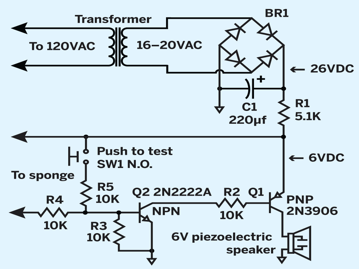
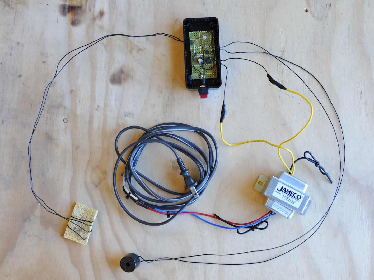
I realized that my two water heaters were 10 years old and started researching water leak detection systems. I soon realized that I could make a system that would work just as well for much less money. Here’s a leak detector circuit I designed that costs less than $25 and draws power from my doorbell transformer. This works nicely because the transformer is already installed in the attic and it’s on 24/7. You can also use a dedicated transformer.

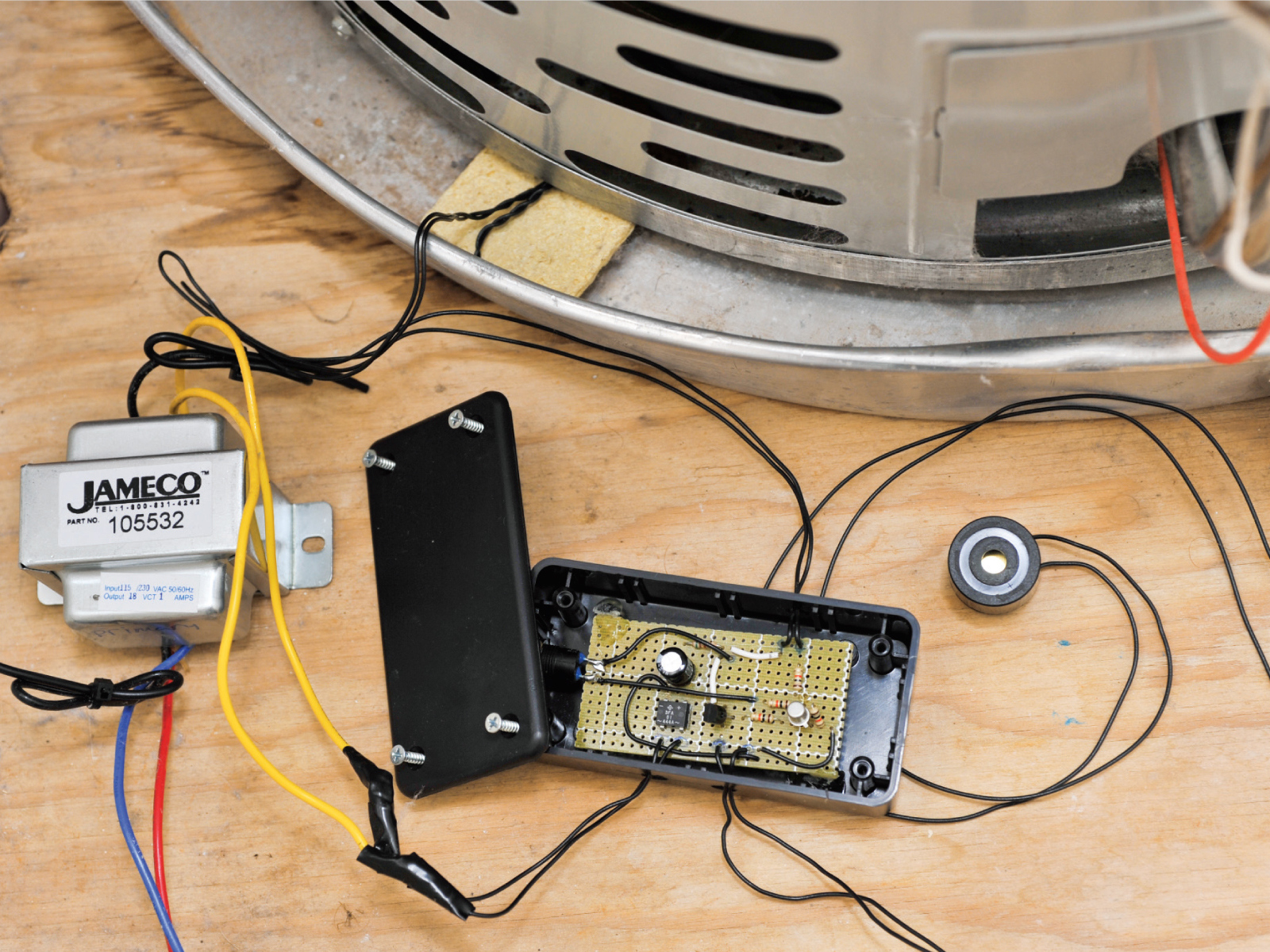
Does this leak detector work? The answer is a big yes. Just a few weeks after I installed it, I came home from work and heard it buzzing. Upon investigation, I discovered that my primary water heater was leaking, and that its drain pan was clogged and already half full. My little circuit had saved the day.

Project Steps

Build the circuit.

Use the schematic for assembling the water leak detector circuit. Start by soldering 2 wires into a bridge rectifier and then a filtering electrolytic capacitor on a small perf board.

This will convert the AC from the transformer to DC with a ripple waveform, with voltage following the formula VAC × 1.414 = VDC (RMS), or about 23V–26V DC.

Continue building the circuit on the board, following the schematic. A 5.1kΩ resistor inline (R1) reduces the 23V–26V AC to 6V, which drives a 6V piezoelectric buzzer when either the push-to-test switch is pressed or water is detected.

Drill a hole in one side of the project box for mounting the push-button switch, and smaller holes in back for mounting the board inside with machine screws. Drill small exit holes for the wires leading to the transformer, the buzzer, and the water probe.

Disconnect the power to your transformer, then connect the 2 wires from the rectifier to the transformer’s secondary side. Finally, connect the piezo buzzer using wires long enough to reach just outside your attic door, or another location where its sound won’t be blocked from the rest of the house.

Install the water probe.

Use a large needle to pierce 2 parallel holes into the side of a sponge, about 2″ deep and 1″ apart. Strip at least 2″ of insulation off 2 pieces of solid copper wire, and insert the bare copper into these holes. Wrap the rest of the wire snugly around the sponge so that the bare copper ends will not come out.

Connect the other ends of the copper wires to the circuit, and lay the sponge in the overflow tray. When hot water leaks and is absorbed by the sponge, the resistance between the 2 bare copper wires drops to about 1MΩ or less. This forward-biases the 2 transistors and causes the piezoelectric buzzer to sound.

If you have multiple water heaters near each other, you can make a probe for each, and connect them all in parallel. You can also use this circuit under dishwashers, garbage disposals, refrigerator icemakers, swimming pools, hot tubs, waterbeds, etc.

Conclusion

This project first appeared in MAKE Volume 28, page 141.