This article first appeared in Make: Volume 41.

Last November, Adafruit Industries’ wearables guru Becky Stern published a “Cell Phone Charging Purse” project that used an inductive power transfer link to wirelessly power a hacked handbag from a base station with a built-in transmitting coil. A receiver was sewn into the bag’s bottom lining and wired to a phone charging cable inside. Keep your phone plugged into the bag, and the bag on the station, and you could just grab the bag any time and go, confident that you were leaving with a fully charged device.

I liked that idea, but wanted to take it a step further — to eliminate plugs from the system altogether. Here’s how I did it.

How it Works

induction-diagram

Wireless battery charging operates on the principle of electromagnetic induction (see “Skill Builder: Induction Instruction). Inductive charging has been a household technology for decades (for instance in electric toothbrushes), but recently has begun appearing in smartphones and other mobile devices.

Though wireless charging is inefficient compared to a wire, it’s faster to connect and disconnect, and it spares wear and tear on plugs and jacks. For reasonable efficiency, the transmitting and receiving coils need to be aligned as closely as possible, but it’s straightforward to add magnets or other mechanical guides to make this easy. The plastic “well” your electric toothbrush sits in on its charging base serves exactly this function.

Thanks to intense competition in the mobile device market, 5V wireless power transmitters and receivers are readily and cheaply available, and my first experiment (Figure A) was simply to “daisy-chain” two of each together to see if an off-the-shelf wireless receiver could power a second wireless power transmitter. Answer? Yes, but not very well: The second transmitter doesn’t really get enough current to operate at spec, and will connect with the second receiver only temperamentally, if at all.

Since these gizmos are manufactured to an industry standard intended to allow diverse bits of hardware to play well together, I reasoned, they should be fairly well behaved (electrically speaking). Could I simply connect 2 transmitters and receivers in parallel (Figure B), like batteries, to increase the current output to a third? Short answer: Yes! It works.

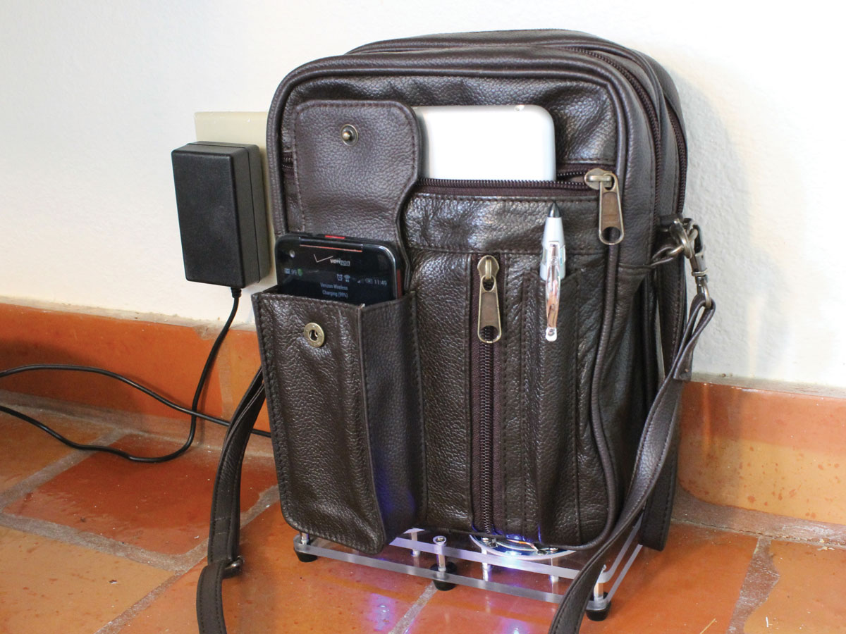
Instead of a single wireless power link, this bag uses two: one to power the bag from the base station, and a second to charge the phone inside the bag. Build this wireless inductive charging bag and your phone may never need a cord again.

Project Steps

Prep the modules

Job one is to solder power and ground leads to all the circuit boards so they’ll be easy to interconnect.

The receivers, which are aftermarket add-ons designed to mount between a smartphone battery and backplate, are very thin devices built on flexible PCBs using tiny surface-mount components. Each comes with 2 small gold-plated contact studs to fit the phone’s built-in terminals. Remove these by heating them up with your soldering iron, then sliding them off the PCB with its tip. Figure out which pad is power and which ground, then solder 8″ of red and black stranded copper wire, respectively, to the pads where the studs used to be. Insulate and secure the 2 solder joints with heat-shrink tubing and electrical tape as needed.

Prep the modules (cont'd)

Remove the cases from the 2 base station transmitters and solder 4″ red and black stranded jumper wires to their input power and ground connections. These PowerBot “coasters” have handy through-hole-plated test points that make this easy; they’re located to either side of the micro USB jack.

Prep the modules (cont'd)

Prepare the transmitter that will be sewn into the bag. Since you’ll be adding a layer of fabric between it and the receiver, first remove and discard the factory case cover to keep from adding too much material between the two coils. Attach 8″ power and ground leads as before. The transmitter I used came with red and black leads presoldered to the main board — all I had to do was desolder and remove the mini USB jack.

TIP: Once you’ve attached power leads to all the modules, take a minute to set up and test the 2-stage wireless power transfer link on your benchtop to understand its operation and verify that all the parts are working correctly.

Install the bag transmitter

Remember that close alignment of transmitting and receiving coils is essential — that’s why you need a bag with a dedicated pocket that closely fits your mobile device. If you’re sewing a bag from scratch, you can just build in the transmitter board as you assemble the bag. If, like me, you’re modding an off-the-shelf bag, you may have to get clever.

Rip out seams as needed to gain access to the bag lining behind the device pocket. Split every second or third stitch with a seam ripper and pull out the little fragments of thread.

Add one or more wiring pass-throughs, as needed, to connect the exposed lining and the bag’s main compartment. Each hole should be wide enough to pass your power and ground leads together, and should be reinforced at the edges so it won’t tear out in use. Sewing buttonholes is a lot of work, so I opted for hammer-set eyelets. I installed one between the lining and the adjacent side pocket, and one more between the side pocket and the main compartment.

Cut down the bag transmitter’s backplate as needed to fit the lining. To prevent snags, smooth off the cut edges and any other protruding case features with a file. Drill a hole in the backplate to provide strain relief, tie a knot in the wires, and pass them through it.

Install the bag transmitter (cont'd)

Align the transmitter behind the device pocket and fix it in place. Depending on your bag design, it may be possible to sew the transmitter right where you want it. In my case it really wasn’t, so I mounted the transmitter, with cement and short screws, to a piece of thin sheet plastic cut to closely fit the lining. Once the seam is sewn up again, the transmitter won’t be able to slip out of alignment with the pocket.

Route the power and ground leads out of the lining via the pass-through.

Temporarily connect a 5V power supply to the transmitter leads and verify that your device charges correctly when inserted into the pocket. Once you’re sure the transmitter-pocket alignment is OK, sew up the lining with the transmitter inside, using a needle and matching thread to replace any seams you ripped out earlier.

Fit the bag receivers

The receiver modules are small, light, thin, and flexible, and easier to install than the transmitter.

Open the bottom lining of the bag’s main compartment. You can rip out a seam, if you like, but it’s faster and easier to just make a cut. The repair may be ugly, but it will be hidden inside

the bag.

Slip the 2 receivers into the bottom lining and fix them in place with fasteners, adhesive, and/or stitches. The bottom lining in my bag fit the receiver modules end-to-end almost exactly, so all I had to do was sew it up.

Connect the dots

To finish the bag, you just have to connect the wiring between the transmitter and the receivers.

Route the wires from the transmitter into the main compartment through your pass-through(s).

Use one wire nut to connect the 3 red leads together, and another to connect the 3 black leads.

Connect the dots (cont'd)

Set up the 2 remaining transmitters on your benchtop and temporarily connect them in parallel to your AC adapter. Put your mobile device in the pocket, then set the bag down on top of the 2 transmitting coils and fiddle with their positioning until all the transmitters and receivers link up and your device starts charging.

Once you’re sure the bag’s wiring is working, tuck the wire nuts and the receiver “pigtails” into the bottom lining, leaving only the transmitter wires protruding. Sew up the bottom lining around them, and the bag is done.

Build the base station

This can be as simple as a flat board with the 2 transmitters glued to its surface. The only really critical factor is that the spacing between the transmitter coils matches that of the bag’s receiver coils as closely as possible.

Experiment with the bag and your mobile device to determine the optimum spacing between the 2 base station transmitters. An ammeter connected between the power supply and the transmitters can be useful here; look for the spacing that gives maximum current draw while the bag is sitting on the base with your device charging in the pocket.

Construct a suitable base station with the 2 transmitters fixed at their optimum spacing and securely wired in parallel to the AC adapter. A simple, attractive design — dimensioned for my parts — is illustrated in the diagram. Itʼs a good idea to seal the coils with a clear coat of epoxy to protect them from wear.

Charge and go!

To use, plug the base station into a wall outlet, put your phone in the bag’s device pocket, and set the bag on the base. The Qi standard recommends that transmitters provide auditory, visual, or tactile indication of a successful alignment; usually this takes the form of an LED that changes color and a short beeping sound. Because this design includes 3 separate power transmitters, each of which makes a sound, it’s easy to tell just by listening if everything has linked up correctly when you set down the bag.