If you should find yourself in need of small volumes of gas at about atmospheric pressure for a reaction or project, generating it on the bench can be a convenient and inexpensive alternative to buying or renting a gas cylinder. It turns out there are a number of useful gas-generating reactions between solid- and liquid-phase reagents, such as:

  • Hydrogen: Zn + HCl —> ZnCl + H2
  • Acetylene: NaC2H + H2O —> NaOH + C2H2
  • Carbon dioxide: CaCO3 + HCl —> CaCl + CO2
  • Hydrogen sulfide: FeS + H2SO4 —> FeSO4 + H2S

Note that any gas-generating reaction, even one that produces a relatively inert gas like carbon dioxide, is potentially dangerous unless performed with adequate ventilation. Depending on the reaction in question, there may be other hazards, and, as always in the laboratory and in life, no procedure should be undertaken unless you understand and are properly prepared for the risks it involves.

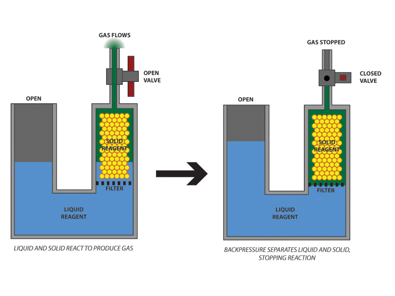
An all-glass reactor for the benchtop production of gases was invented in the 19th century by Petrus Jacobus Kipp, who is known today primarily for this achievement. Kipp’s design incorporates the clever feature that stopping the flow of gas separates the liquid and solid reagents inside the instrument and thereby stops the reaction. Thus the generator only produces gas when you need it, and may remain in a stable equilibrium state on the bench for days at a time, ready to resume operation as soon as you open the valve.

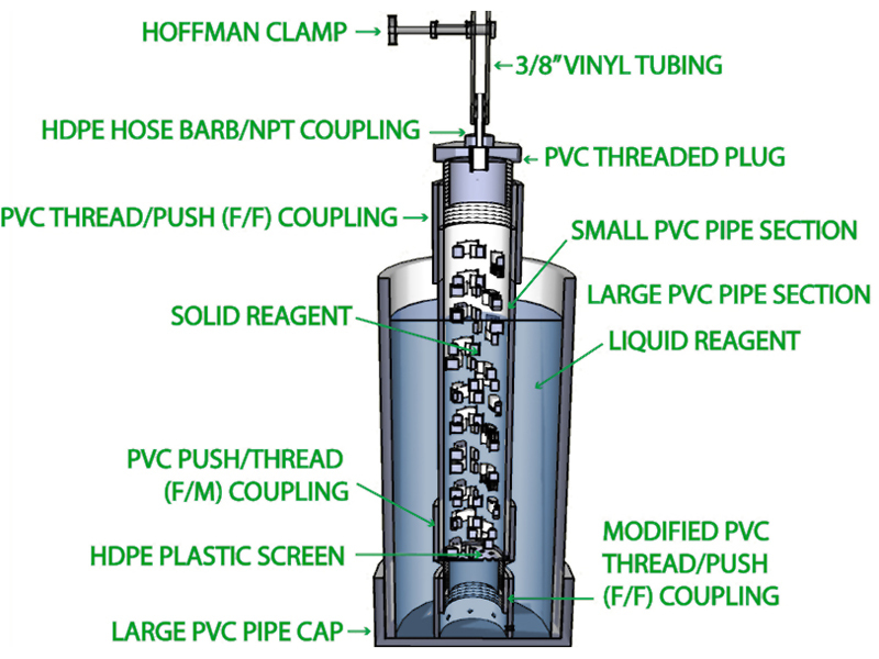
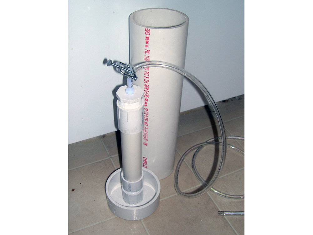
Being made of glass, however, a proper Kipp generator is an expensive piece of apparatus, with new models costing upwards of $250US as of this writing. However, as the useful gas-generating reactions are usually aqueous, rather than organic, an all-plastic Kipp generator is almost as useful as a glass version. PVC pipe is inexpensive, durable, ubiquitous, and easily and securely joined using cement made for that purpose. Demountable PVC fittings are available in a wide variety of shapes and sizes and can be used to provide the necessary “dismantlability” for loading solid reagent into the device. Presented here is my design for such a low cost Kipp generator, with instructions for its construction.

What will the next generation of Make: look like? We’re inviting you to shape the future by investing in Make:. By becoming an investor, you help decide what’s next. The future of Make: is in your hands. Learn More.

Project Steps

Understand how it works

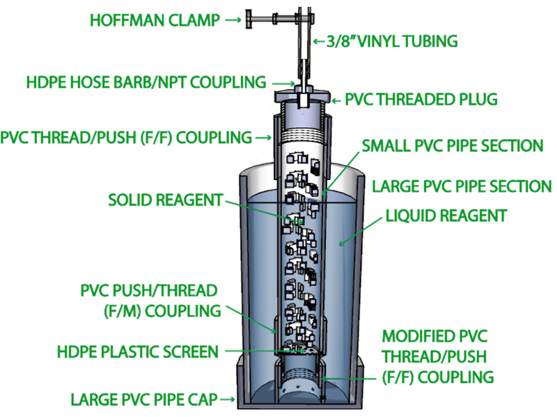
Essentially, the generator consists of a closed chamber, loaded with solid reagent, which communicates with a liquid reagent reservoir at one end, and from which gas escapes at the other. The liquid reservoir is open to the atmosphere, and thus the pressure of gas generated is limited by the hydrostatic pressure of the reservoir column. When the gas valve is closed, gas pressure backs up in the chamber and pushes the liquid reagent back out of the chamber, where the solid phase is retained, thus halting the reaction. Excess gas bubbles out into the atmosphere through the liquid reservoir.

My design features a radial construction which, albeit slightly more complex than the “u-tube” design, offers some advantages over it. Foremost of these is that the radial design makes it possible to remove the chamber full of solid reagent without removing the liquid reagent first. So, if necessary, the chamber can be removed and reloaded without the hassle of pouring off the liquid phase.

Prepare lower coupling

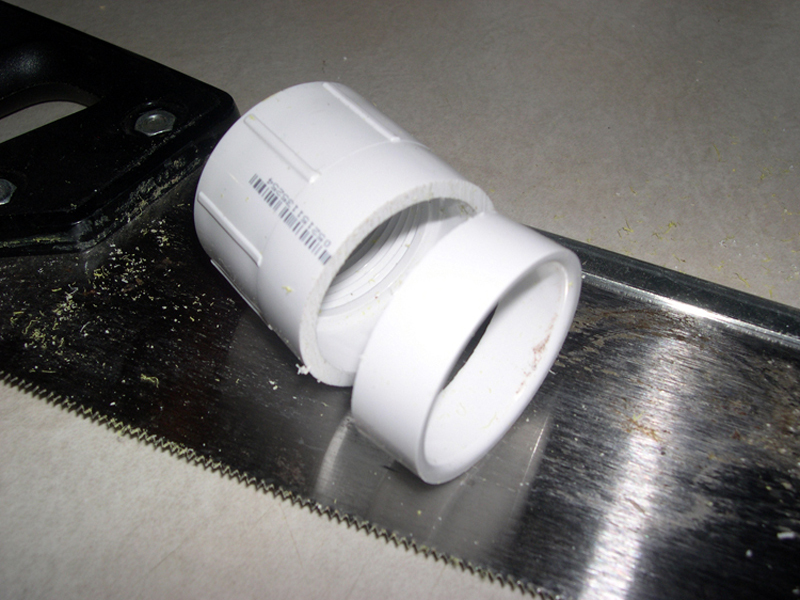
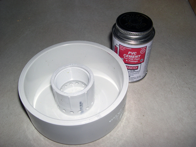
Modify one of the two F/F couplings by sawing through it about halfway along the length of the unthreaded end. This is done to expose a larger surface for cementing the butt joint between the coupling and the large pipe cap, and to reduce “dead height” at the base of the reaction chamber.

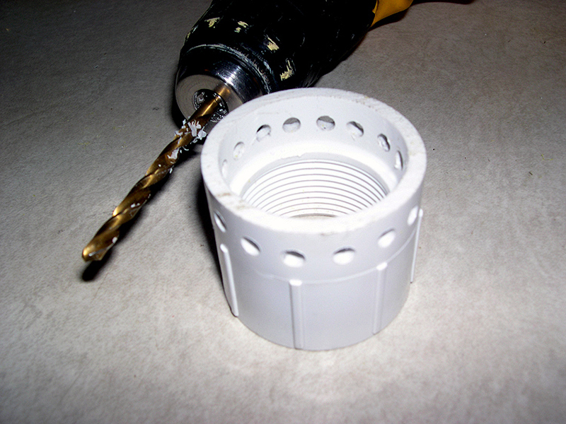
Modify the coupling further by drilling 16 or more ~3/16″ holes around the freshly-cut edge, as shown in the photo. These holes allow the outer liquid reservoir to communicate with the inner reaction chamber.

Install lower coupling

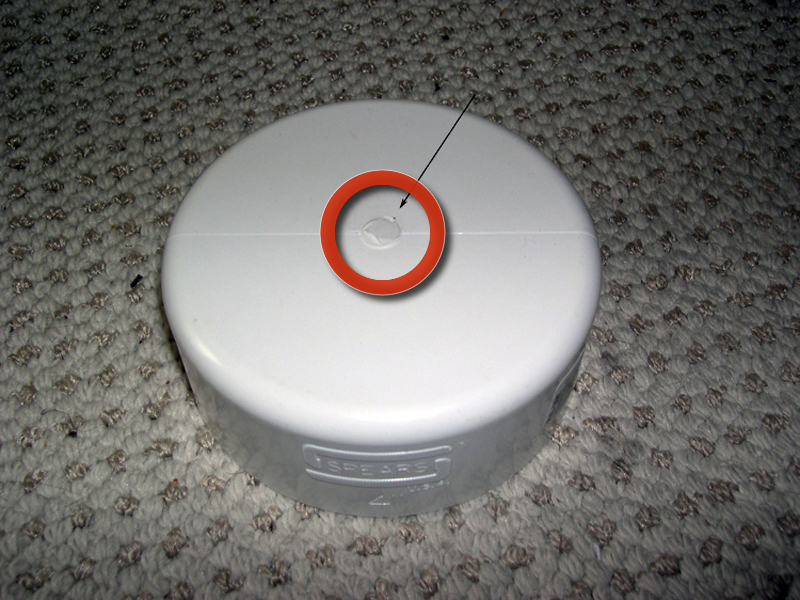
First, remove the raised mold mark from the center of the PVC pipe cap so that it will rest flat on a surface. I used a sharp wood chisel and hand pressure for this operation.

Center the cut-and-drilled lower coupling inside the large pipe cap and cement as shown.

Make plastic screen

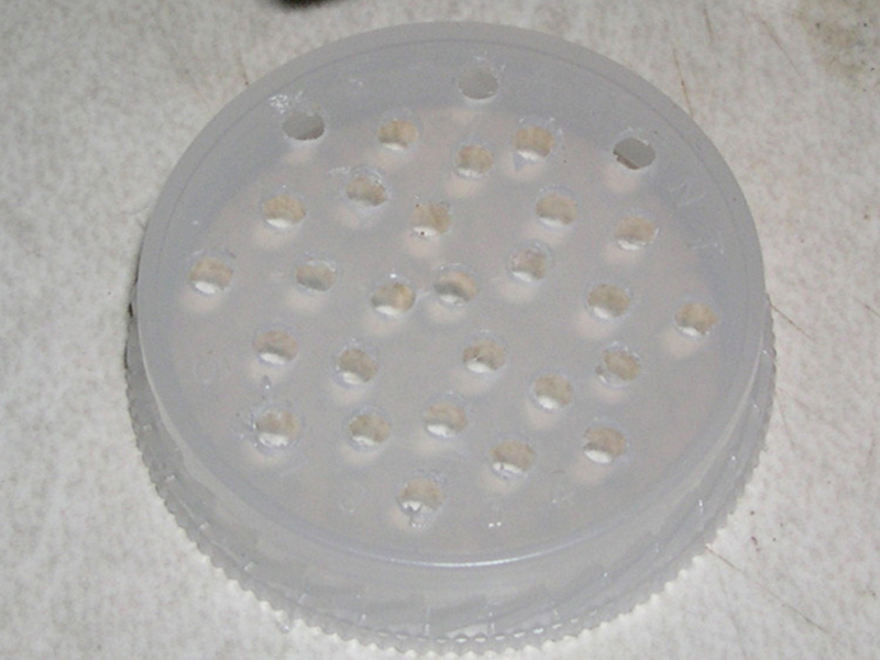
Drill a bunch of ~1/8″ holes in the plastic screen disk to make it porous, as shown.

Clean any burrs raised by the drill off the holes with a hobby knife.

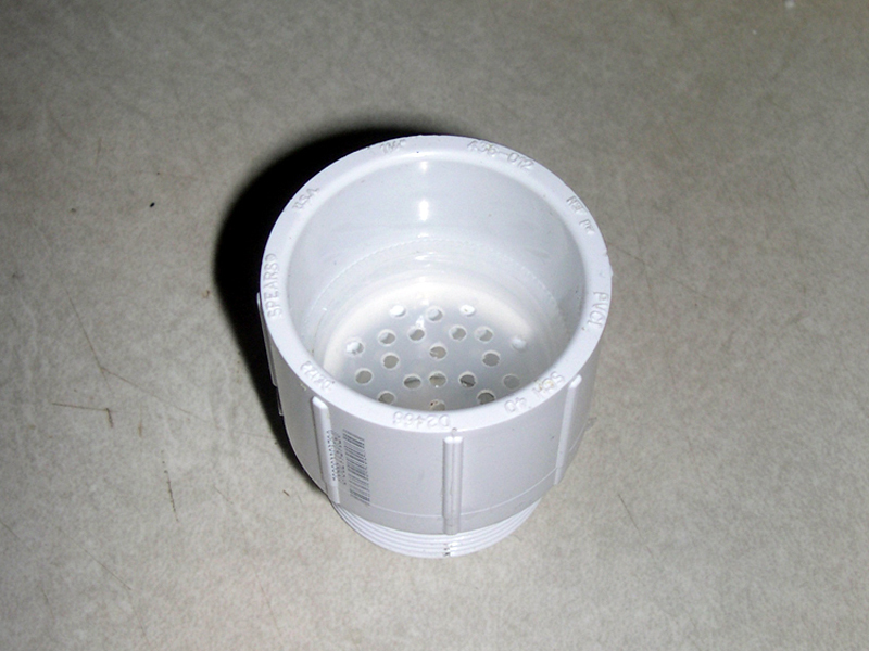
Insert the disk into the F/M coupling, as shown. It should not be able to fall through, but obviously the fit does not have to be liquid-tight.

Mount hose barb

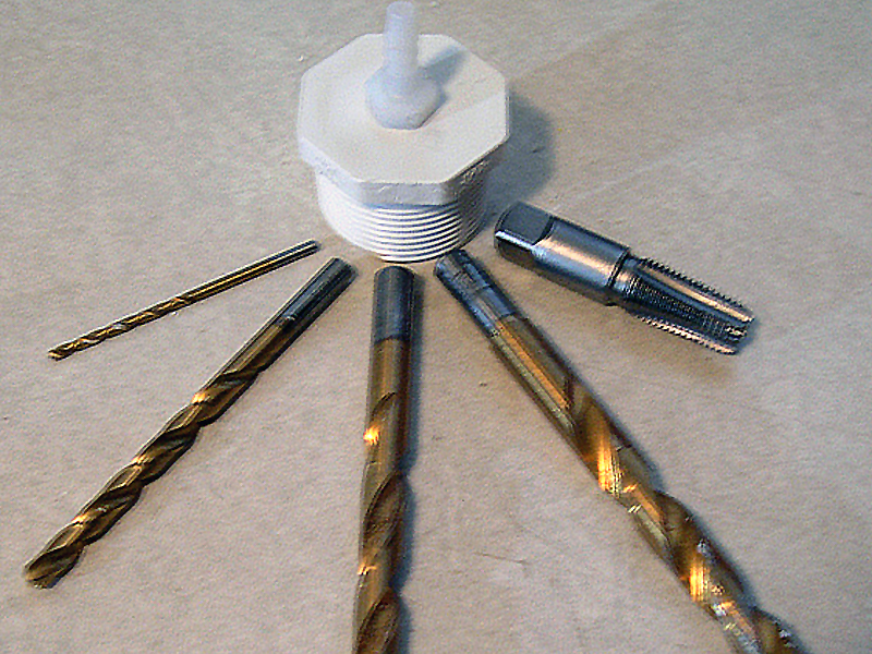
Drill a hole in the center of the threaded plug. Start with a 1/8″ bit and step-drill up to 9/16″.

Tap the hole with a 3/8″ NPT pipe tap.

Apply PVC cement to the barb’s threaded end and tighten it into the hole.

This joint should be as gas-tight as possible to keep the inactive generator from leaking over time.

Assemble

Assemble the reaction chamber first.

Cement one end of the small pipe section into the unthreaded end of the M/F coupling, on top of the filter element you made in Step 4, securing the filter in place.

Cement the push-fit end of the unmodified F/F coupling to the pipe’s other end.

Cement one end of the large pipe section into the large pipe cap.

Fill the large pipe section with water and let it stand overnight to test the joint you just made.

Load the solid reagent

Load the reaction chamber with your solid reagent. I used chunks of washed limestone, gathered from the ground, about 1″ across on average, and filled the pipe about halfway up.

Close the reaction chamber by screwing in the threaded plug at the top. A smear of silicone grease on the threads will help with removal, later, and will help to insure a gas-tight seal.

Screw the loaded reaction chamber into the threaded coupling at the bottom of the reservoir.

Use

Before performing this or any other chemical reaction, put on latex or nitrile gloves, goggles, and other appropriate protective clothing. Work with plenty of ventilation, within shouting distance of another person who knows, in advance, to check on you at regular intervals.

Prepare your liquid reagent. I used 10% hydrochloric acid prepared from concentrated hardware store muriatic acid using safe technique. If you don’t know what safe technique is, get someone who does to show you.

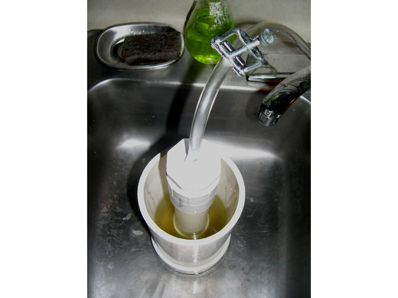
Secure the generator against the possibility of tipping. Clamping to a rigid object or resting in a sink are viable options; both would be better.

Thread the vinyl tubing through your compression clamp, and attach it to the hose barb. The clamp should be open so gas can flow through the tubing.

Slowly add your liquid reagent, in portions, monitoring the evolution of gas from the end of the tube. Submerging it in water and observing the bubbles may be a convenient way to do this.

You can regulate or temporarily stop the flow of gas by adjusting the compression valve. The first time you close it, use caution, and be aware that back-pressure from the gas will be vented as bubbles in the reservoir, and this venting will continue until the reaction stops. When you open the valve again, the gas-generating reaction should continue.

Conclusion

Besides any reaction-specific cautions that may be advisable, please be aware of the following potential hazards when using this device:

  • Asphyxiation - The generation or release of gases other than oxygen in an enclosed space creates a real danger of asphyxiation. Be sure to have adequate ventilation.
  • Spattering - Back pressure in the reaction chamber, especially when the valve is first closed, will cause excess gas to bubble up through the liquid reservoir. This bubbling can be vigorous, and may spatter the liquid reagent if the reservoir is filled too high.
  • Tipping - Although the generator is designed to be free-standing, a clamp, brace, or other support is highly recommended. An unsupported generator will spill the liquid reagent if it is accidentally tipped over.