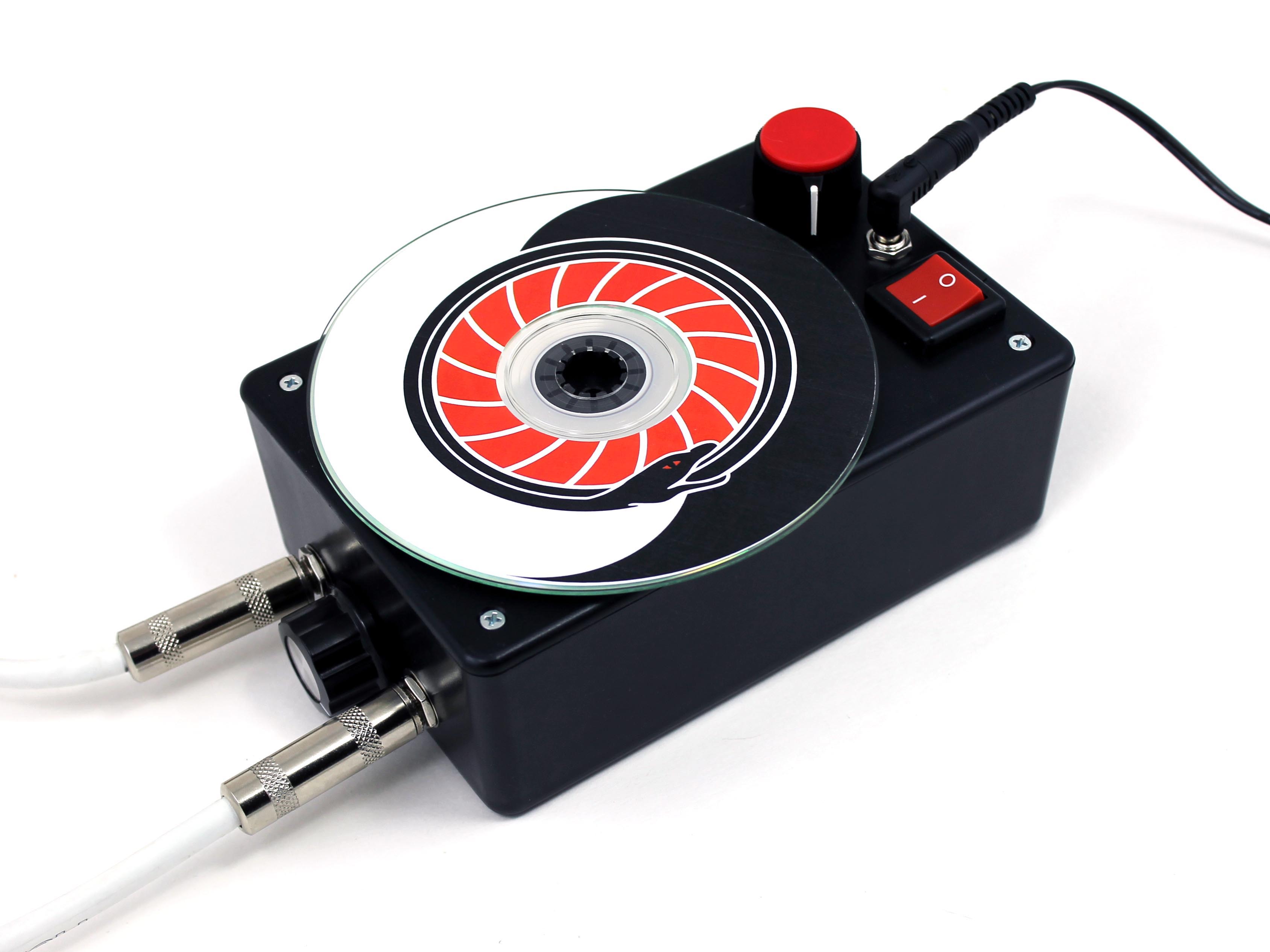
The optical tremolo is a simple but powerful musical instrument FX box that reads a pattern printed on a rotating disc and converts it into a volume-modulating “tremolo” sound. Changing the sound of the effect is as simple as changing the pattern on the disc, which you can do by drawing, painting, taping, or applying a printed label directly to its surface. The idea is based on a concept proposed by Charles Platt in his 2009 book Make: Electronics.

The original Optical Tremolo Box is one of the more popular projects we’ve ever published. It was designed to be easy to build, requiring only minimal soldering. If you’re a newcomer to electronics and are interested in experimenting with this effect, that build is still a great place to get started.
On the other hand, if you’ve got a bit more experience under your belt, you may be interested in a more powerful design without the easy-bake compromises. Optical Tremolo 2.0, as we call it, improves upon the original build in a number of ways:
- It runs at 9V DC from a single power supply. 9V is the universal stompbox standard. You can plug Optical Tremolo 2.0 directly into your off-the-shelf pedal power supply, or run it from a 9V battery, rechargeable or otherwise.
- It uses an efficient motor speed controller instead of a rheostat. A series resistor is an extremely simple and easy way to regulate motor speed, but it’s also crude — it wastes power as heat, and will burn up if overdriven. Our Dial-a-Speed motor controller uses pulse-width modulation (PWM) to switch motor power on and off for varying lengths of time, many times a second. PWM motor regulation provides much more stable and reliable control, especially at the low speeds that produce the most interesting tremolo effects.
- It uses a brushless motor. Brushless motors are less noisy, both acoustically and electrically, than traditional brushed DC motors. Here we’re using an off-the-shelf brushless case fan, which comes ready-made with a hub for mounting the tremolo disc without having to mess around with a motor shaft or shaft coupler.
- It operates using reflected light, instead of transmitted light. In this configuration, the emitter and detector can be on the same side of the disc without an awkward “stalk” projecting from the top of the enclosure. Even better, the tremolo patterns can be printed on standard white paper instead of the relatively hard-to-find and expensive printable transparency stock.
- It accepts blank or scrap CDs/DVDs as tremolo discs. This allows a ready-made CD hub to be mounted for easy disc swapping. Also, off-the-shelf printable CD/DVD labels are easily adapted for creating your own original tremolo patterns and art.
HOW IT WORKS
This project uses our Dial-a-Speed all-in-one motor controller knob design. If you haven’t built a Dial-a-Speed or don’t want to, a number of inexpensive ready-made or kit-built PWM controllers are available for small DC motors.

The switch turns power on or off for the “dirty” circuit, which consists of the motor speed controller, the motor, the sensor head, and one-half of the opto-isolator. The disc carrying the tremolo pattern spins on the motor hub, at a speed regulated by the motor controller, presenting the pattern to the sensor head as it turns. The sensor head has an infrared (IR) LED emitter and an IR photodiode detector mounted side-by-side. IR light from the emitter is reflected by white or light-colored areas on the disc surface, and absorbed by black or dark areas. The amount of IR light reflected back to the detector varies the current passing through it, which in turn varies the signal passed to the base of the NPN transistor. The base is wired “normally high” so that the transistor is switched on in the absence of reflected IR. More reflected IR tends to turn the transistor off, with the net effect that darker areas of the tremolo pattern give more volume damping, and brighter areas give less.
The transistor switches a bright white LED sealed together with a cadmium sulfide (CdS) photoresistor inside a piece of heat-shrink tubing in an opto-isolator arrangement. The photoresistor is connected in series with a 50K potentiometer between the audio signal line and ground. This “clean” circuit is not connected to Vcc, which helps prevent motor switching or other power supply noise from contaminating the audio signal. When the LED is on, the photoresistor is strongly illuminated and its resistance is low, effectively shorting the audio signal to ground and muting its volume. The series potentiometer serves as “mixer” for this effect — when its resistance is high, the contribution of the photoresistor is less significant and the tremolo effect is less noticeable; when the pot’s resistance is low, the contribution of the photoresistor (and the tremolo effect) are correspondingly stronger.


