It’s now possible to build remote, low-power microcontroller projects that can operate indefinitely without batteries and still not crash, even if power is interrupted. Let that sink in.

Subscribe to Make: for this and more projects and articles.

As an example, we’ll show you how to build a LoRa-based weather station that’s powered solely by solar panels. Its code is written in CircuitPython, running on a popular hobby-grade microcontroller board: the Adafruit Metro M0 Express. The novelty is that it can keep the state of the weather measurement program, even during periods of complete darkness when it runs out of power. This is called intermittent computing or perpetual computing, and it opens up a new world of sustainable electronics, where many applications will work well, and practically forever, without reliance on a battery.

The trick is a specially modified version of the CircuitPython interpreter that is resilient to power failures. (Not the language — the CircuitPython syntax stays intact). This means we don’t have to supply our weather station with a continuous power source, such as a battery. Instead, we harvest energy from a solar cell and temporarily store it in a capacitor. The system will boot when the capacitor contains enough energy to execute some code, and the program will pick up where it left off before the power ran out. This way, we can opportunistically collect weather information without relying on a potentially polluting battery and frequent travel to replace that battery.

Finally we can build truly perpetual, battery-free, energy-autonomous embedded systems using off-the-shelf components! We proved the concept in 2020 with our Battery Free Game Boy project led by Jasper de Winkel, where we powered the game by solar panels and kinetic energy from the player’s button presses. Now we’ve brought it to CircuitPython.

We call our system BFree. You can program your microcontroller in regular CircuitPython, and a specially designed extension board stores the intermediate state of the computation during power failures. Then your microcontroller can pick up where it left off, and continue executing CircuitPython correctly when power resumes!

Battery Free Game Boy, September 2020, from Proceedings of the ACM on Interactive, Mobile, Wearable and Ubiquitous Technologies

How Does BFree Work?

BFree is two things: an extension board (“shield”) attached on top of the Metro M0 Express and a piece of software running transparently on the Metro M0. This combination enables CircuitPython applications written for the Metro M0 to continue where they left off after a power failure. BFree is designed to operate in an environment with insufficient energy to continuously power the Adafruit Metro M0.

The BFree shield houses a Texas Instruments MSP430FR series microcontroller. What’s special about this MCU is the presence of non-volatile RAM in the form of ferromagnetic RAM (FRAM). This type of non-volatile memory is low-power and byte-addressable. It functions just like standard SRAM, but with the bonus of not losing its data when power is removed. It is a better choice than flash memory, which is power-consuming to write and requires writing of a complete “page” at a time.

The BFree software is a modified version of CircuitPython (which we call BFree-core) that talks with the BFree shield over an SPI connection. BFree has several available checkpoint strategies for when and what to store in the shield’s FRAM memory from the CircuitPython program. The default strategy is creating a checkpoint every 100ms, but this can all be configured within CircuitPython.

When BFree-core decides it’s time for a checkpoint, it instructs the BFree shield to make one, and sends the CircuitPython Virtual Machine’s content to the shield, which stores it in non-volatile memory so that BFree-core can fetch it when power is restored. The shield’s microcontroller also acts as a memory controller, so that a valid checkpoint of the CircuitPython program is always available, even if power fails while creating a new checkpoint!

Additionally, the shield houses the energy harvesting system needed to provide BFree with bursts of energy. A capacitor on the board is connected to an energy harvesting source, such as a solar panel. The harvesting source will slowly charge the capacitor. When the voltage of the capacitor reaches a (configurable) threshold, a boost converter is enabled to supply the rest of BFree with constant 3.3V supply. When an on-board BFree comparator notices that the boost converter cannot maintain the target voltage of 3.3V, the boost converter is disabled, power to the Metro M0 is cut, and the charge cycle starts again.

To protect BFree from a harvesting source that produces too much energy, i.e. greater than 3.3V, the shield is equipped with over-voltage protection circuitry. This circuit dumps any surplus energy in a power resistor located on the back of the shield. This way, no energy is lost during typical operating conditions

For more details, see our paper, and the schematic diagrams.

What will the next generation of Make: look like? We’re inviting you to shape the future by investing in Make:. By becoming an investor, you help decide what’s next. The future of Make: is in your hands. Learn More.

Project Steps

Build Your BFree Shield

The BFree shield isn’t for sale yet, as it originates from a recent academic project. But you can build your own, using the open-source Eagle design files and component list. Fabrication houses like OSHPark and PCBWay will make the PCB for you for a few bucks.

Flash the Metro and Shield Firmware

Next you’ll flash the BFree shield and the Metro M0 Express board with new firmware, so they can work together to restore a CircuitPython program after a power failure.

Follow the instructions at the Github repository to program your BFree shield with its pre-compiled .elf firmware file. (Optionally, the complete source code for the BFree shield, and how to build it from source.)

The BFree-compatible version of CircuitPython is called BFree-core. Download the pre-compiled .elf version of BFree-core, from the folder Metro M0 Express BFree Firmware at the Weather Station repo. Then use your serial wire debugger/programmer to flash BFree-core to the Metro M0 board, following the instructions here. We recommend using the debugger, not the Metro M0 bootloader, because BFree-core is still in development, and you’ll want the debugger to recover from a broken CircuitPython state (if it ever happens).

Test Your BFree Shield

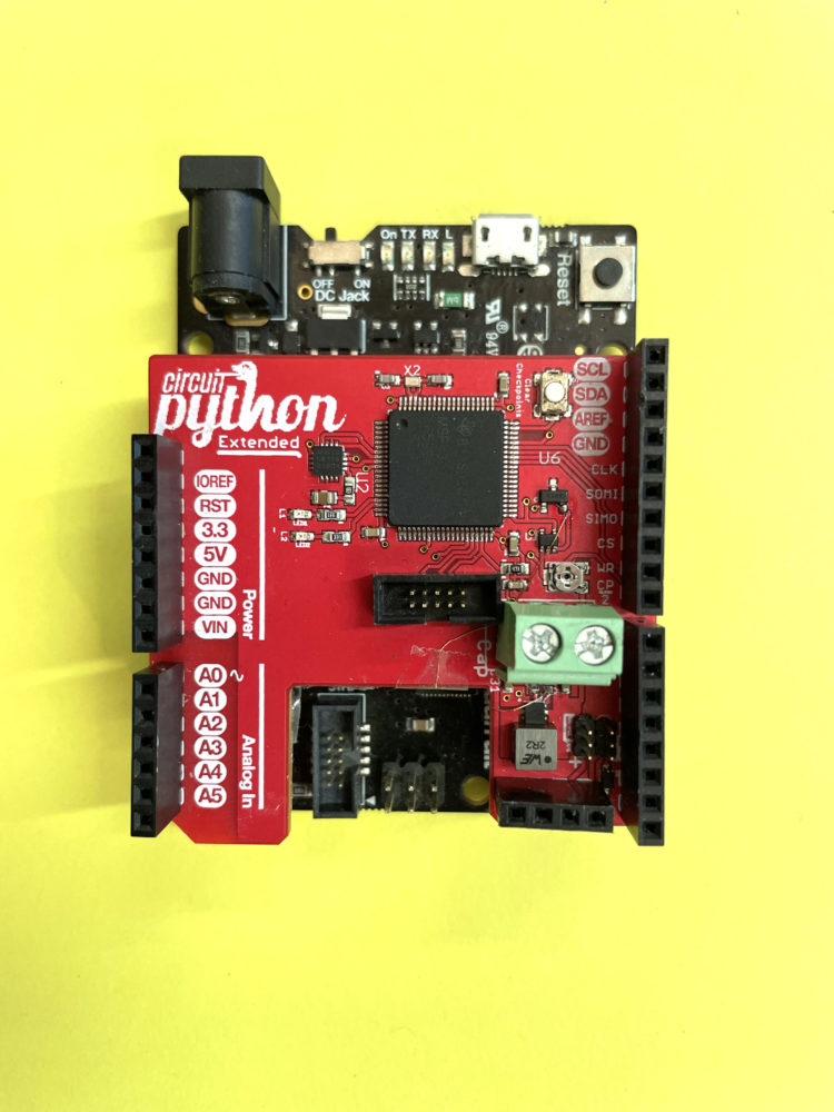
Figure A

Attach the BFree shield on top of the Metro M0 (Figure A). The pins of the shield correspond one-to-one with the headers of the Metro.

Next, connect the Metro’s USB port to your PC. The Metro should show up as a mountable device in your operating system as usual.

Now we’ll verify that BFree works as intended, using the Test Code program from the Weather Station repo:

import time

# Setting the counter to 0 will only

# happen the very first boot

counter = 0

# The battery-free program should

# continue counting somewhere in the

while loop

while True:

counter += ١

print(‘Counter =’, counter)

time.sleep(1)

This simple CircuitPython program increments a variable counter indefinitely. In a typical solar-powered system, the battery will deplete when there’s no sun. At this point, the counter will be reset to the initial value of zero. However, in the BFree-based solar-powered system, the counter will continue increasing from where it left off, once the system recharges after a power outage. To see this effect in action, upload the Test Code to the Metro M0 board, replacing the original main.py program pre-installed on the Metro with this new one. Do not disconnect the Metro from the USB port, and don’t forget to keep the BFree shield connected on top of the Metro M0.

Now monitor the serial port, letting the code run for several seconds. (If you’re not sure how, check this.)

Unplug the Metro M0 from the USB port (cutting off power) and plug it back in again. When the Metro is plugged back in, the counter should continue where it left off instead of resetting back to zero. It’s sustaining the computation state despite power failures!

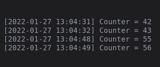
Figure B

Figure B shows the serial connection monitored by Minicom (type sudo apt install minicom to install it) with 1-second timestamps. You’ll see that the counter does not reset to zero when the system is unplugged, and that there’s a gap between Counter = 43 and Counter = 55. This is because the Metro M0 with its BFree shield is already continuing the CircuitPython program execution (incrementing the counter) before the USB serial port is even completely initialized.

Connect Sensors to Metro Through BFree

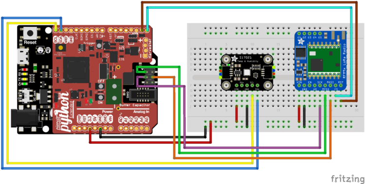
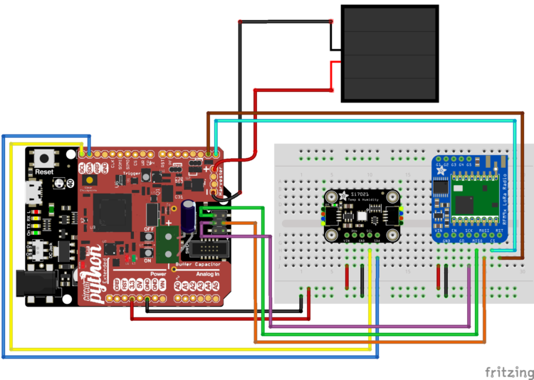
Now let’s set up the weather station. Follow the wiring diagram (Figure C) to connect the Si7021 temperature and humidity sensor module (black) and the RFM9x LoRa transceiver (blue) to your BFree shield on top of the Metro M0.

Before running your weather station from the solar panel, let’s test that everything works on constant power. Connect the Metro to your computer, and upload the Battery Free Transmitter code from the Weather Station repo. This new main.py program accumulates temperature and humidity samples, averages them, and sends them as a LoRa packet in a continuous, non-breakable loop.

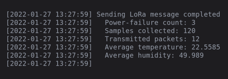
Now monitor the serial port as you connect and disconnect the Metro from your computer. Whenever the station broadcasts a LoRa message, it will also print a message to the serial port containing all the information sent in the LoRa frame and the number of samples collected since the start of the program (Figure D).

Figure D

Set up the Lora Receiver

Figure E

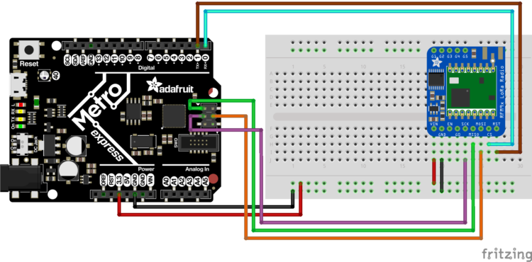
Now that your LoRa transmitter is working, you need a receiver. Connect the second RFM9x LoRa transceiver directly to the second Metro M0 Express board, using the same pins as before (Figures E and F). This receiver will be permanently connected to a PC via a USB port and continuously listen for LoRa frames sent by your weather station.

Figure F

Upload the Receiver code to the Metro M0, from the Weather Station repo. Now whenever your weather station has power and decides to send a message, your receiver should be ready to receive the message, parse it, and print it to the serial terminal.

Test the Lora Communication

Before you go battery-free, you should test whether your transmitter and receiver are working as expected on constant power. Connect them both to your PC through individual USB ports, and monitor the serial port that belongs to the receiver. You should see the received messages as shown in Figure G.

Figure G

Make it Battery Free

Now that everything works on continuous power, you can make your weather station battery-free! You’ll use a solar panel to harvest the required energy and buffer this in a supercapacitor until it gathers enough energy to run a portion of the code.

Multiple factors come into play when choosing the size of the solar panel and supercapacitor. How much energy a solar panel generates dramatically depends on the available light. The same panel can generate 200mA of current when placed in direct sun, but only 0.5mA under office lighting. So if you plan to use your weather station outside, pick a reasonably small solar cell; use a larger one if you use it indoors. Any surplus energy, once the supercapacitor is full, is dumped into a large power resistor on the back of BFree, so make sure your solar cell doesn’t exceed 1.5 watts or this resistor might get too warm.

The capacitor determines how much energy your weather station can store. A larger capacitor can keep the station operating for longer, but also takes longer to charge, so the time between two successive intervals where BFree executes code is longer. If you choose to use a supercapacitor instead of a normal capacitor, check the equivalent series resistance (ESR) value. You ideally want to use a capacitor with an ESR below 5 ohms (5Ω). We chose a 0.22F supercapacitor with an ESR of 2.5Ω for our setup.

Figure H

Connect your supercapacitor to the terminal block on the BFree shield, shown in dark green in Figure H. Make sure to pay attention to the capacitor polarity. Then connect your solar panel to the header labeled Harvester.
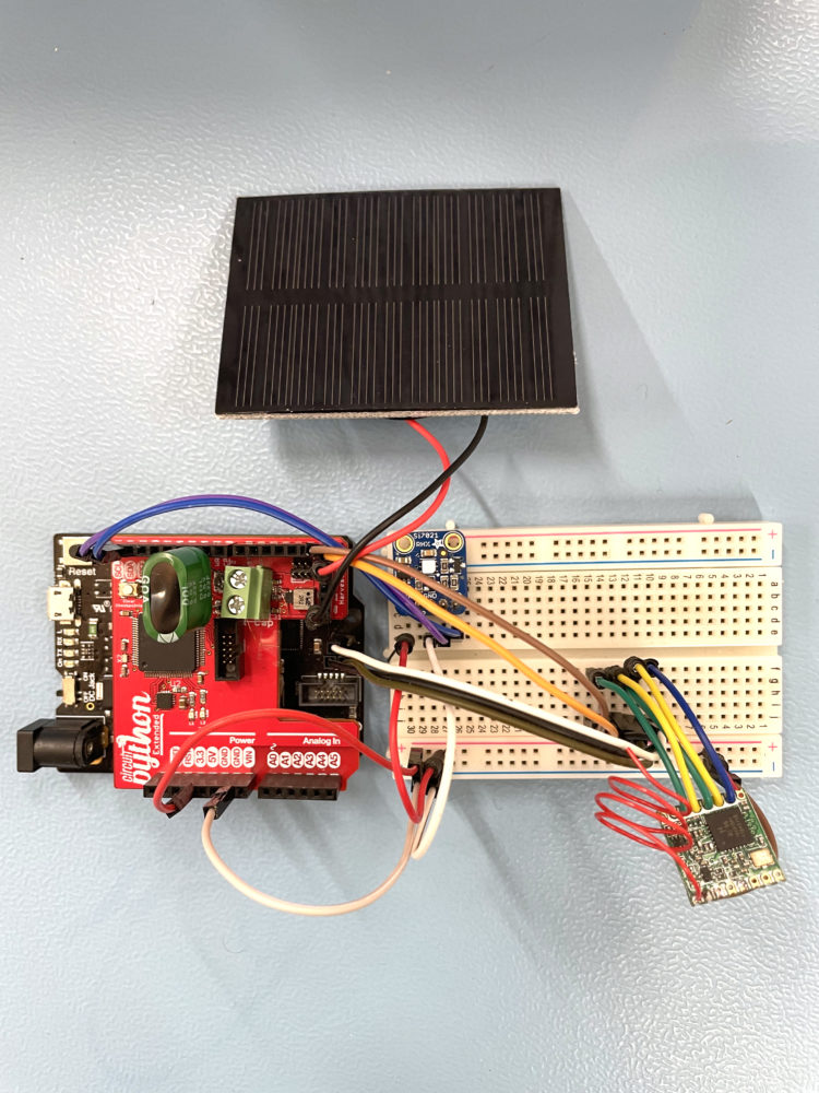
Figure I

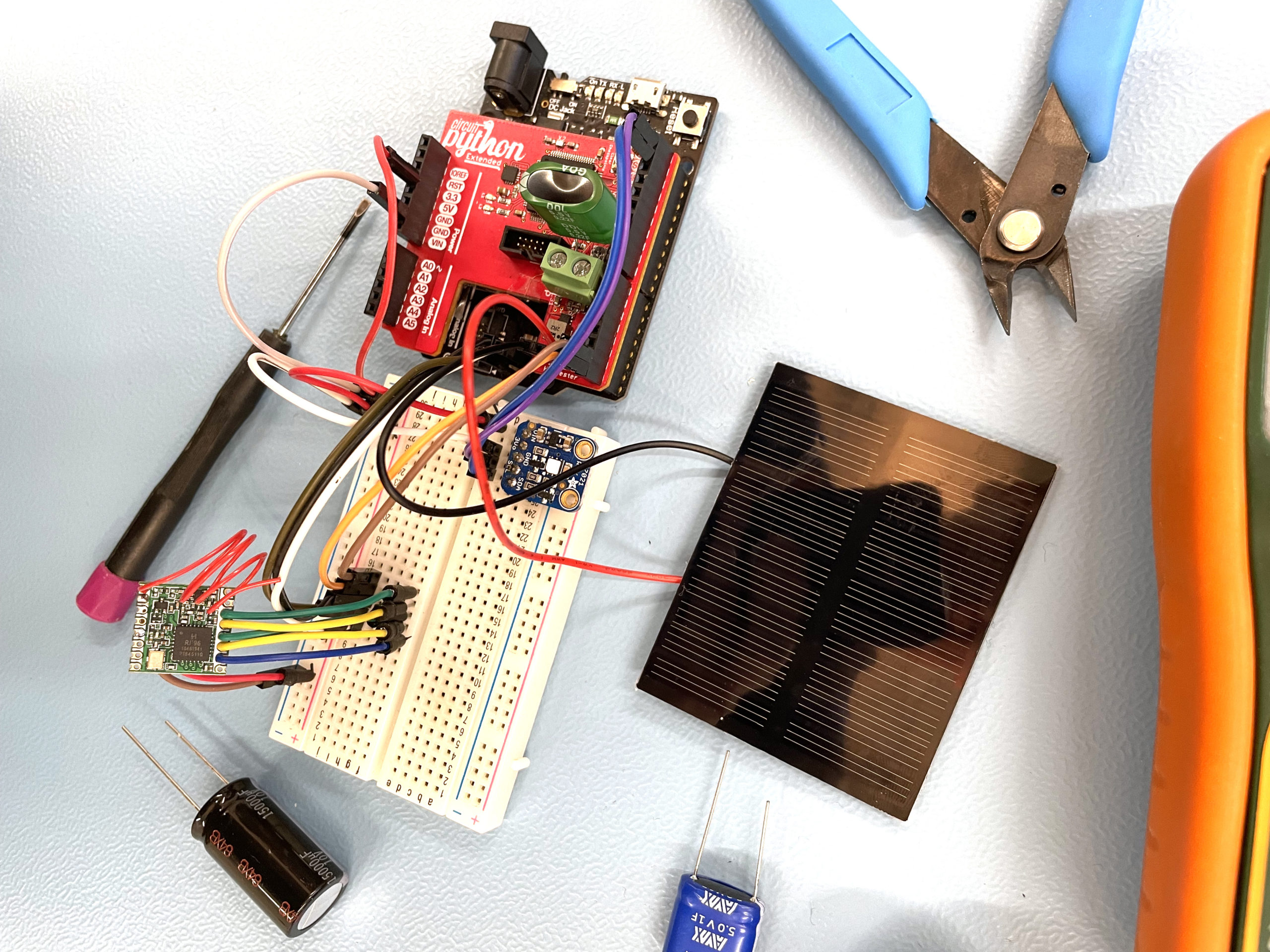
Your weather station is ready to go (Figure I)!

Conclusion

Set it and Forget it

Deploy your perpetual weather station somewhere that receives light, and it should run virtually forever. When the capacitor reaches its threshold voltage, the system will turn on for a couple of seconds. During this time, the CircuitPython code will continue to either collect sensor data, process that data, or transmit a LoRa message. How often a message is sent greatly depends on the available light and can vary between once per second when the sun is intense and once every 15 minutes when there’s only office lighting available.

GOING FURTHER

In this project we connected the solar cell directly to the BFree shield. For better harvesting efficiency, you could connect a maximum power point tracking (MPPT) charge controller between the solar cell and the shield’s harvester input.

Solar cells are not the only form of energy harvesting that can be used. It’s also possible to harvest power from radio waves, kinetic energy, piezoelectricity, heat energy, or other ambient sources (see sidebar).

We hope you enjoy building this weather station, and we hope you’re convinced now that battery-free electronic devices are possible with intermittent computing! Of course this is just a beginning. Battery-free remote control? Battery-free stock price display? You name it! We would love to hear about your experience and your ideas. Please send all of them as Github feature requests here.

BFree was developed by Vito Kortbeek and Przemysław Pawełczak at TU Delft, Netherlands; Kasim Sinan Yildirim at TU Delft and the University of Trento, Italy; and
Josiah David Hester, Abu Bakar, and Stefany Cruz at Northwestern University, USA. 


Dedicated Energy Harvesting Chips

As energy harvesting has become more prevalent for low-voltage IoT and smart devices, chip makers have integrated the discrete components required to efficiently harvest the most energy possible onto a single chip to optimize size and performance. Now, anyone can buy chips and breakout boards from Digi-Key, SparkFun, and Adafruit that can harvest solar, piezoelectric, thermal, and even radio wave energy. These ICs range in sophistication (and price) from simple step-down or step-up voltage regulators to much more sophisticated chips with built-in rectifiers or maximum power point tracking (MPPT).

What is maximum power point tracking? It’s a complex topic, with significant research continuing across industry and academia. The problem is that the efficiency of power harvesting of any source is affected by the environment (i.e., amount of sunlight, device temperature) and the load (i.e., how much power is being drawn). An MPPT tries to dynamically change the load that the harvester sees, so that the maximum power is extracted. This is extraordinarily hard to do well!

One of the more common (and older) of these chips is the Texas Instruments BQ25504, available on various breakout boards. It has a built-in MPPT, buck-boost regulator, and in some variants, internal circuitry to manage the recharging of a battery or a supercapacitor. Linear Technologies LTC3588 has also been around for a while (Figure J). It combines a rectifier circuit and a buck converter to harvest piezoelectric or solar sources that produce a high voltage (10V–40V) and low current.
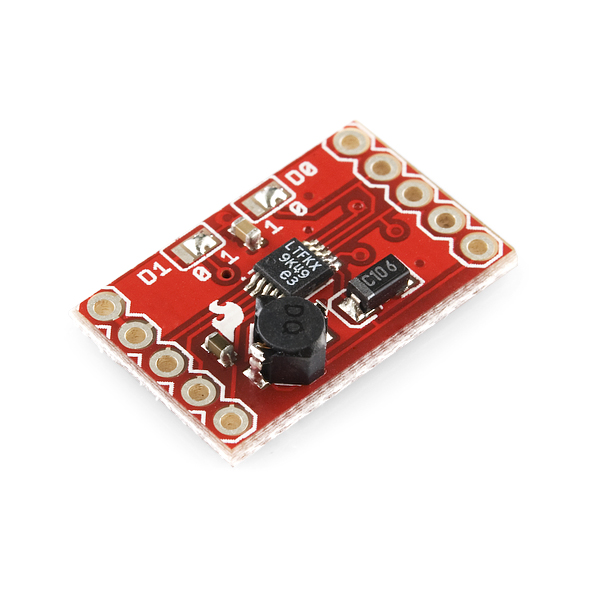
Figure J

Some exciting directions are being explored by startups who are tackling the unique constraints of mobile devices and ultra-low-power systems. For example, newer harvesting ICs like the Nowi Energy NH2D0245 (Figure K) optimize for higher MPPT efficiency and conduct a much faster calculation of the maximum power point, which means they can harvest more energy in dynamic environments, for example, on a wristwatch. You can buy the bare chip from Digi-Key or request a breakout board here.
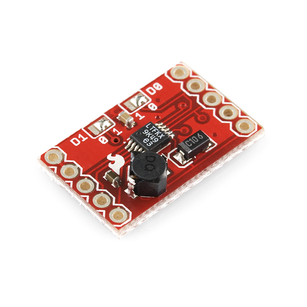
Figure K

Other startups are fine-tuning chips for emerging harvesting sources. Matrix Industries’ Mercury boost converters, available from Digi-Key and Mouser, are custom-built to harvest energy from tiny thermoelectric generators (TEGs), aka Seebeck generators, which generate an electrical current based on the difference in temperature on the top and bottom of the TEG. These have notoriously low output voltages, which have to be boosted to be of any use. Matrix’s Prometheus modules are designed to harvest from thermoelectric sources even at insanely low voltages (6mV).

The emergence of these custom chips, many available for makers and hobbyists in nicely designed breakout boards, make it an exciting time to be making energy harvesting projects!

—Josiah David Hester