


Maybe you’ve seen a persistence-of-vision (POV) illusion before: an array of bright LEDs on the spokes of a spinning bicycle wheel that magically paints colorful animations, light effects, and messages in the night. These visual effects are always good for a “Wow!” — but we’ll go them one better and build a 3-dimensional illusion: the POV Globe.
The term persistence of vision refers to a phenomenon of human vision: a light stimulus lingers as an aftereffect on the retina for about 1/10 of a second. When light stimuli are sequenced in rapid succession, they merge into one continuous image. Scientists still argue how much of this phenomenon is shared between the eye and the brain, but the effect is real — in fact it’s the basis for film and television.
In most POV displays, a linear (1-dimensional) array of LED lights rotates around a single point, like a bike wheel. By measuring their rotation rate and controlling their flashes with millisecond precision, we can create the illusion of a 2-dimensional image lingering in thin air.
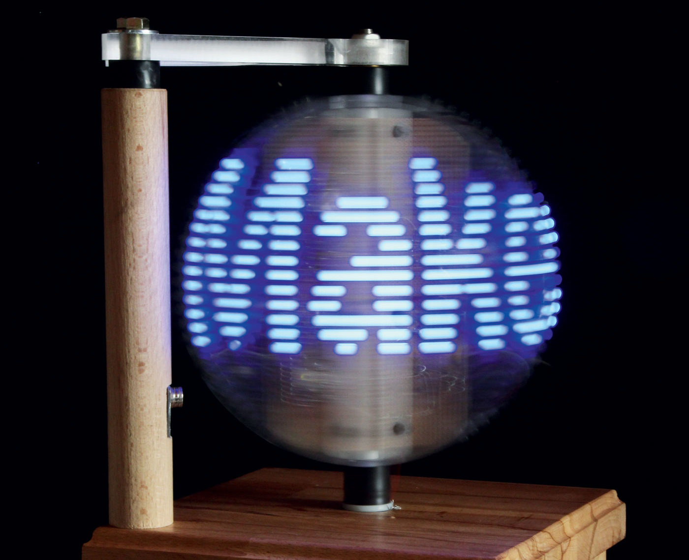
In our POV Globe, we’re adding a new dimension. We rotate a curved array of LEDs around a rotational axis, like a planet. When the flashing LEDs draw images in the air — say, the continents of the Earth — the result is a 3-dimensional, spherical illusion: a globe! Of course, our globe can make other images — like the Death Star from Star Wars, a skull, or the Make: logo — appear magically in the room. It all depends on the perfect timing of the LEDs.

This project has 4 main parts: the electronics, which control at least 24–40 LEDs using an Arduino Nano microcontroller and 74HC595 shift registers; the POV Calculator software that breaks down an image into a bit-pattern that your globe can display; the Arduino sketch that breaks this pattern into segments and sends it to the shift registers; and, finally, the mechanics that rotate the LEDs. It’s a moderately difficult project, but with a little experience on the soldering iron and some woodworking and metalworking skills, it can be accomplished in a weekend.
The microcontroller’s job is to issue a predetermined pattern of binary pixels to the large number of LEDs. This data must be sent synchronously with the ring’s rotation, triggered by a magnetic field sensor (a Hall effect probe). But the Arduino has relatively few output pins, so we resort to a trick: We use simple shift register chips, which collect the serially transmitted data (8 bits per chip) and on command make the data parallel (available all at once) at their output pins. This strategy takes advantage of the Arduino’s high-speed serial (SPI) pins, requires much less programming effort, and greatly simplifies the wiring.
This build is just a suggestion. Once your first globe is working, you’re sure to come up with ideas for extensions or modifications. We couldn’t stop at just one!