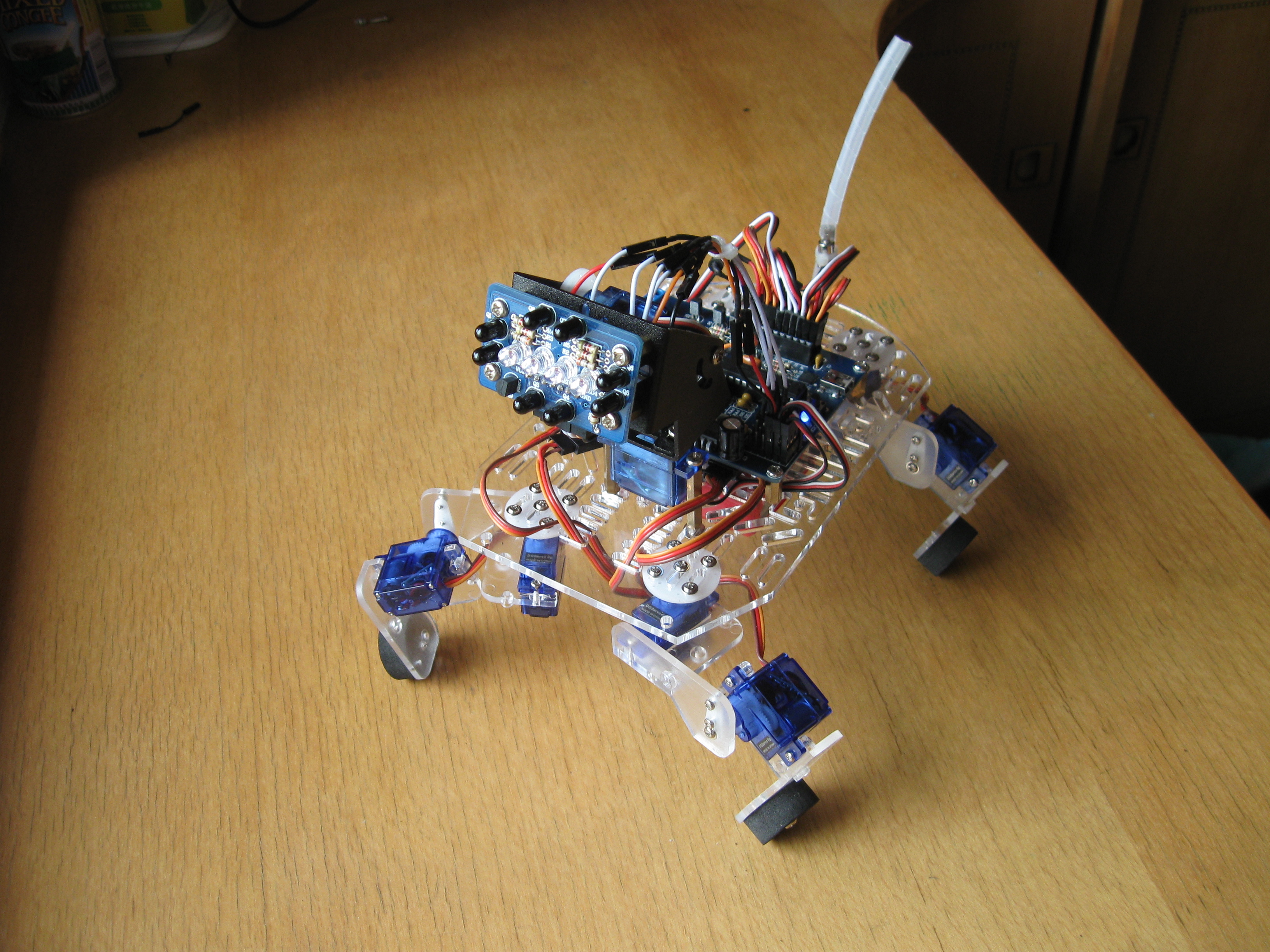
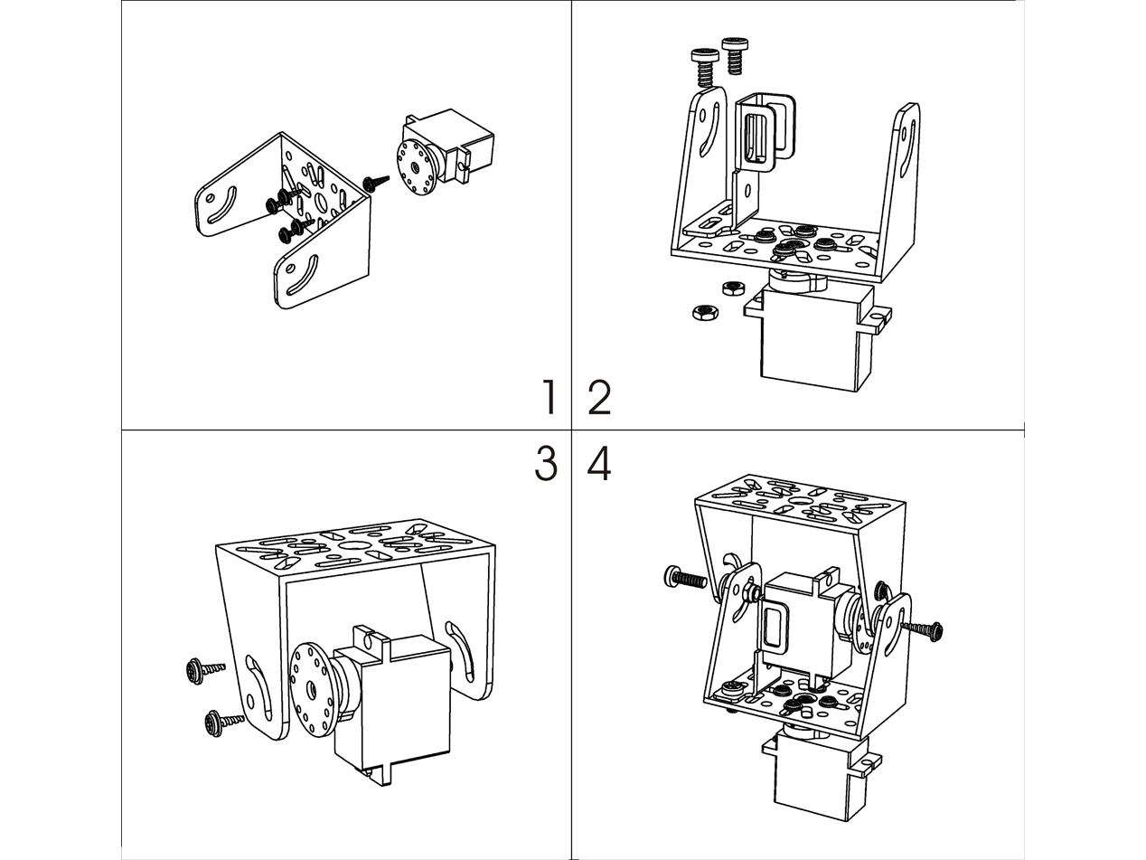
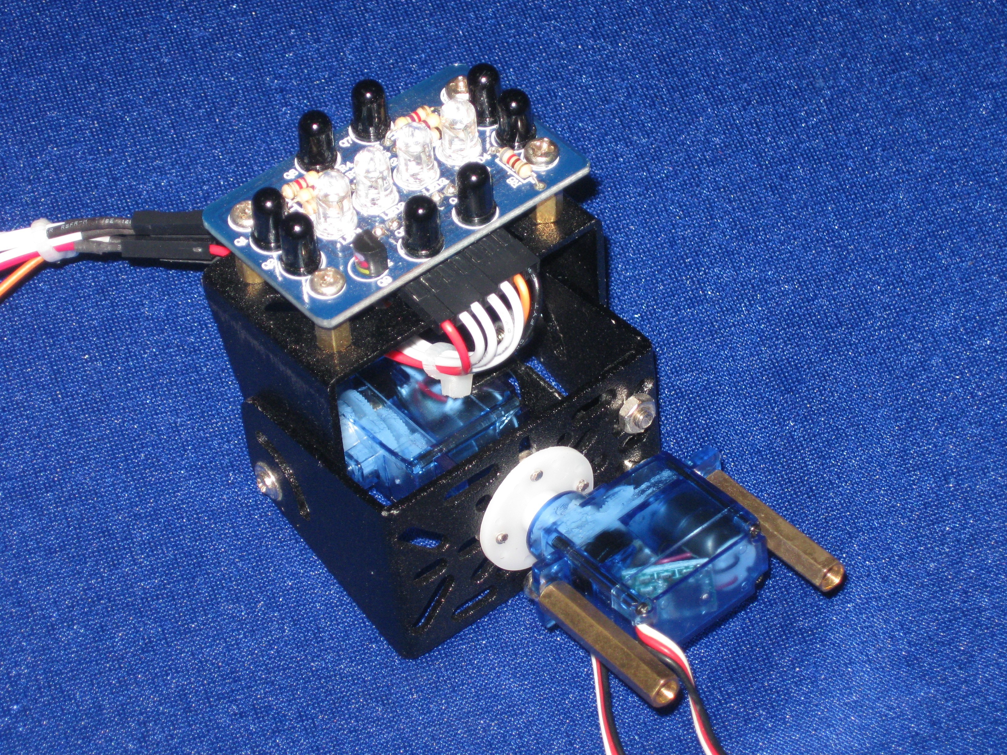
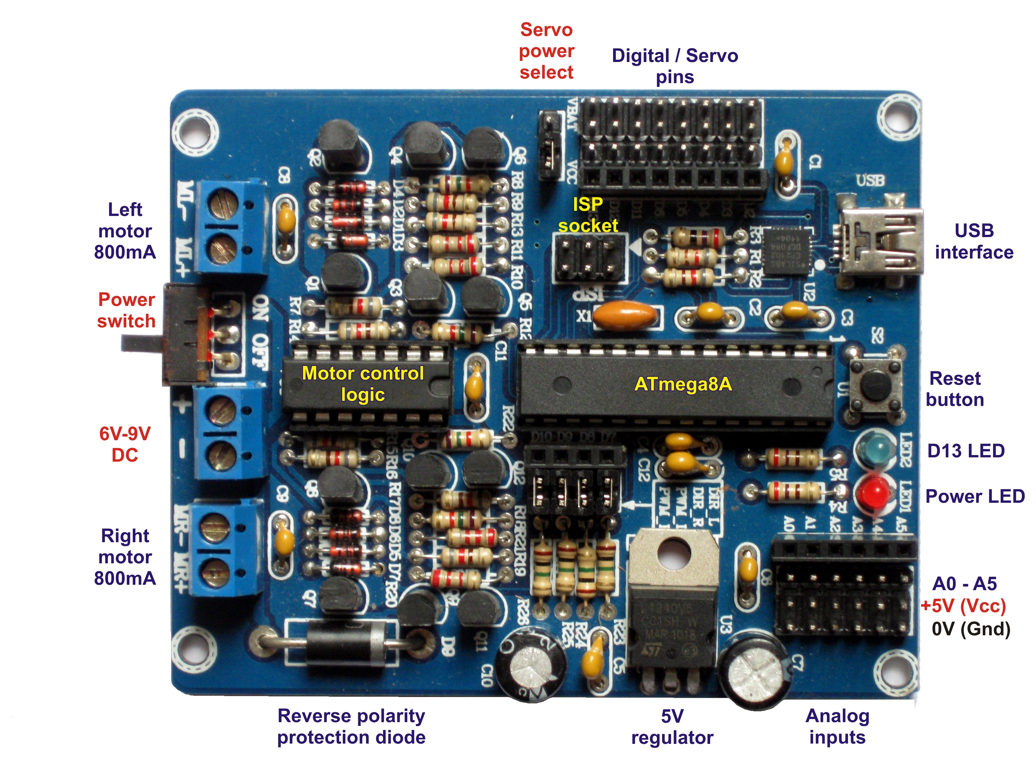
Wire the head to the analog inputs so that A0 is top, A1 is left, A2 is bottom, A3 is right, A4 is pan and A5 is tilt. Make sure the white/orange wire from the servos connects to the pin closest to the female header. The control wire for the IR LEDs connects to D8. Remove the the jumpers for D8 and D10 to isolate the right motor control circuit.
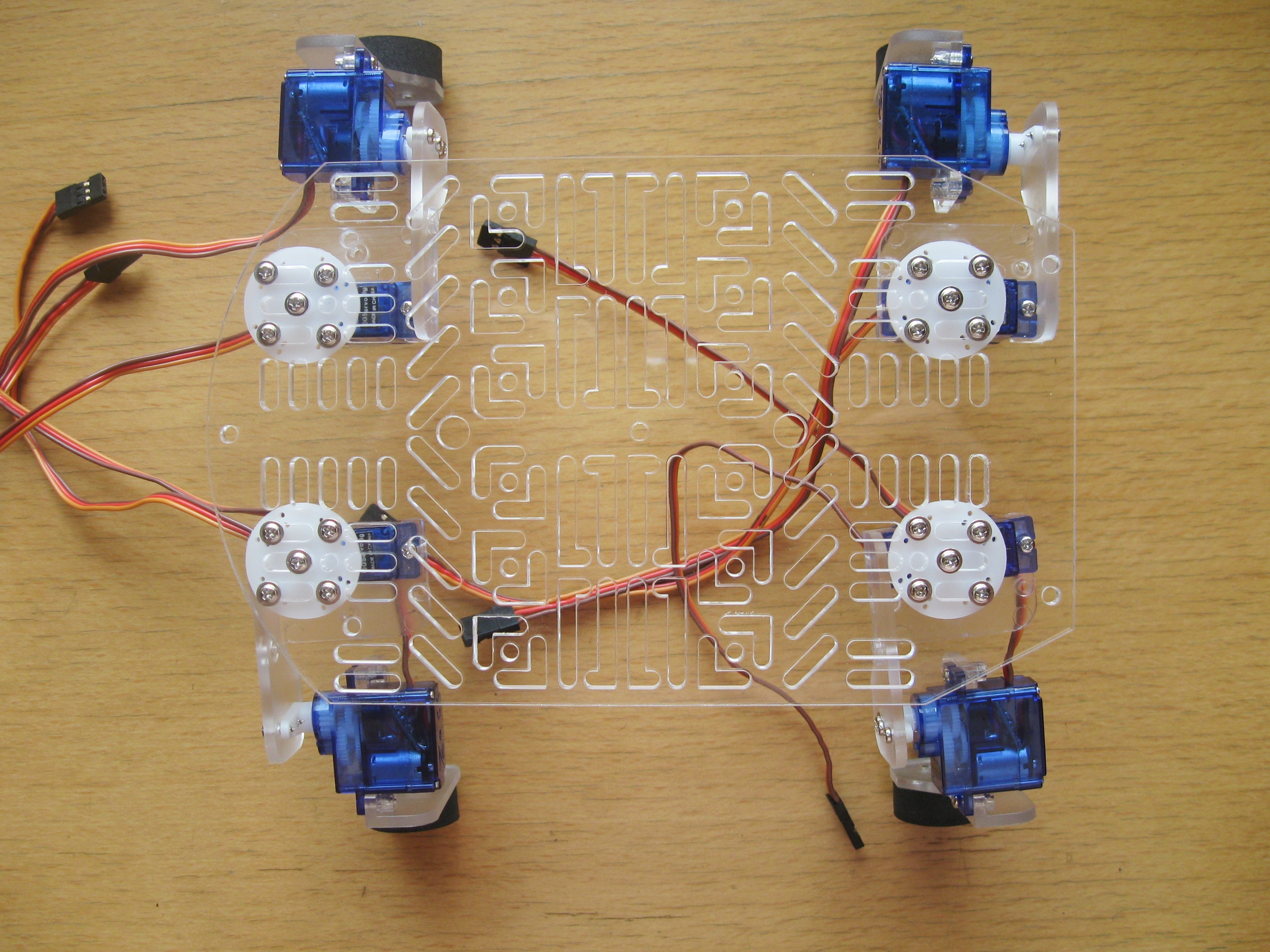
Connect your hip and knee servos next. D2 is the rear left hip, D3 is the rear left knee, D4 is the front left hip, D5 is the front left knee, D6 is the front right knee, D11 is the front right hip, D12 is the rear right knee and D13 is the rear right hip. Once again have your white/orange signal wire closest to the female header.
The pan and tilt servos are powered from the 5V regulator as they are connected to the analog pins but your legs need more power!
The legs can draw about 3A when doing strenuous work so they are connected to the battery by two 3A diodes (1N5400). These diodes reduce the battery voltage by about 0.7V each and the LiPo has a nominal voltage of 7.4V so the end result is that the servos get the 6V they are rated for. One of the diodes is the reverse-polarity protection diode on the controller. The second diode we fit in place of the servo power selection jumper.
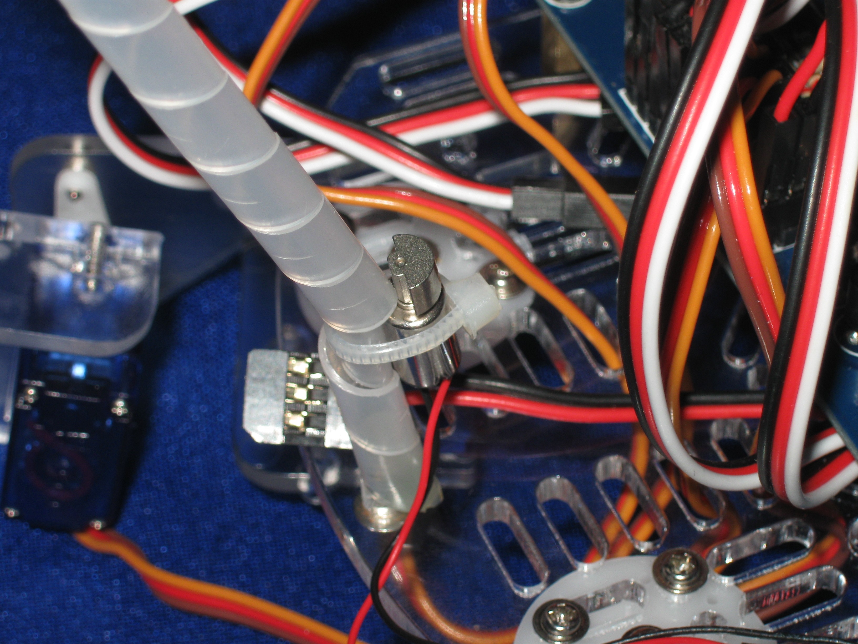
Fortunately for us the legs on a 1N5400 diode are just a tiny bit thicker than a male header pin so we can use two short female-to-female jumper wires to connect our diode to the PCB without soldering. If you’re using NiMH batteries, which are heavier, then you can leave this diode out. The servos will be running at 6.6V but this is necessary for the robot to stand on its hind legs.
Admittedly, when the LiPo is fully charged (8.4V) your servos will get 7V and may get a bit hot. If you live in a warm climate and wish to extend the life of your servos then you can add a second diode in series giving you 6.3V when the battery is fully charged and 5.3V nominal. My robot works fine and the temperature is above 30°C.


