Like it or not, Bluetooth headsets have become a part of our lives. Formerly worn only by stuffy corporate execs and the social elite, these devices have become ubiquitous, thanks to dropping prices and hands-free driving laws. A quick search online shows that a new Bluetooth headset can be purchased for less than $20. This is great news for makers because now we can use them in all sorts of projects!

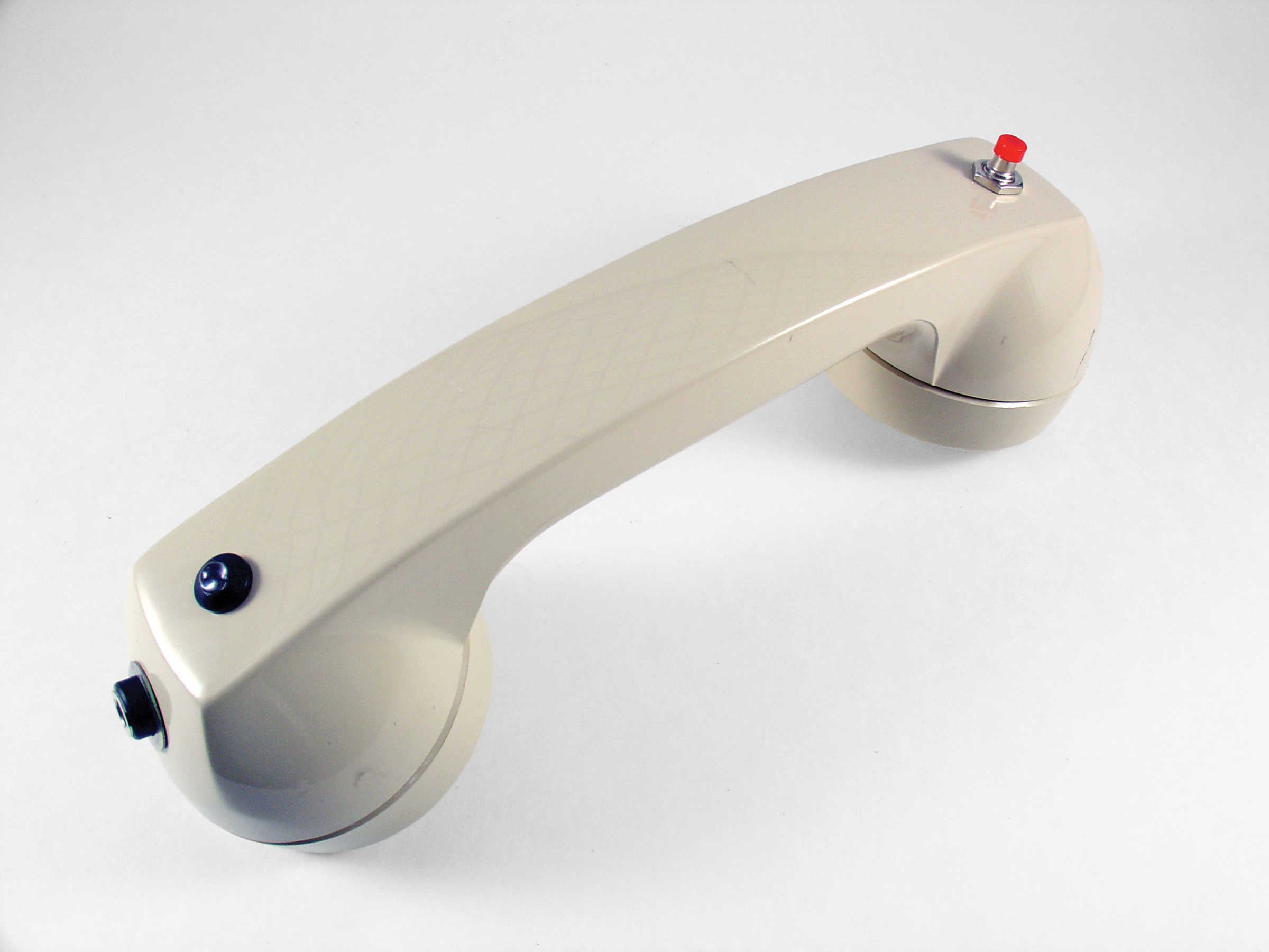
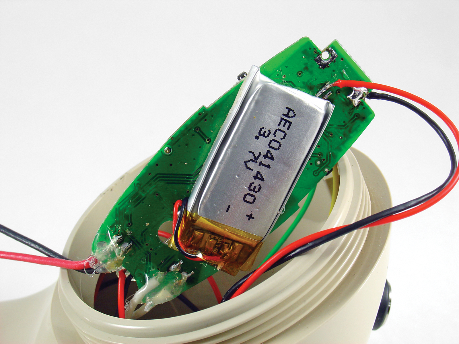
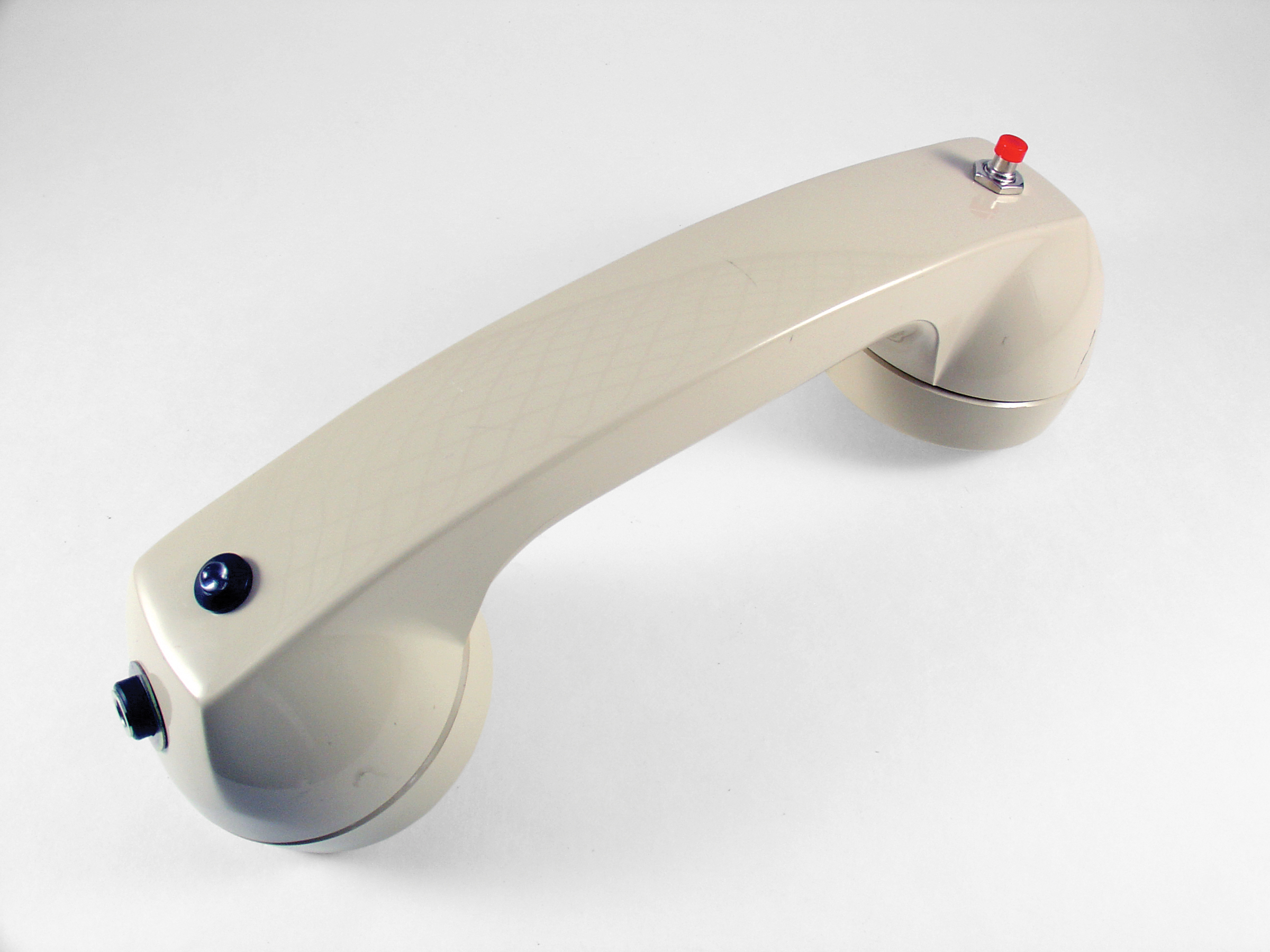
My wife gave me her old Motorola HS820 Bluetooth headset when she upgraded to a newer model. Of course, I immediately tore it open. Inside, I found a small printed circuit board, a lithium polymer (LiPo) battery, an electret microphone, and a tiny speaker. I came across a vintage ITT telephone handset on a recent trip to Weird Stuff Warehouse in Sunnyvale, Calif. The instant I saw it, I knew exactly what to do: stick the guts of the Bluetooth headset inside and create a retro Bluetooth handset!

What will the next generation of Make: look like? We’re inviting you to shape the future by investing in Make:. By becoming an investor, you help decide what’s next. The future of Make: is in your hands. Learn More.

Project Steps

Open and prepare the Bluetooth headset.

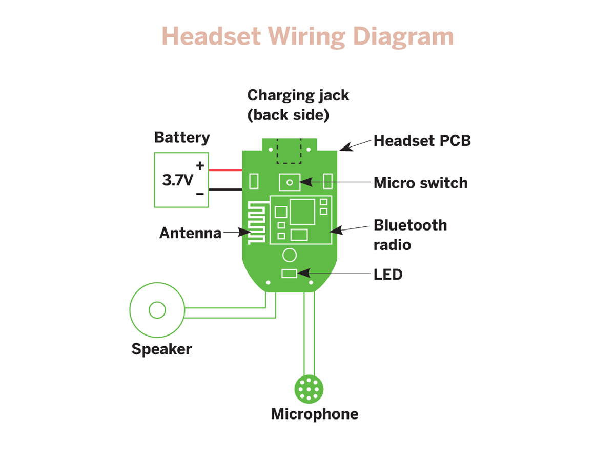
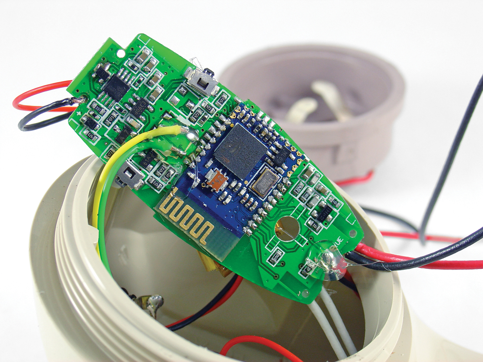
Remove the screws on the back of the headset and pry the case open, exposing the printed circuit board (PCB) and wiring inside. Make a diagram showing where the wires for the speaker, microphone, and battery connect to the PCB.

The polarity of the battery is important, so be sure to mark where the red (positive) wire goes. Unsolder all the wires, starting with the battery. Make sure the battery wires don’t short together. I used a piece of tape to keep them safely apart.

NOTE: Not all Bluetooth headsets are the same. Yours may differ slightly from that shown but will likely have all of the same parts.

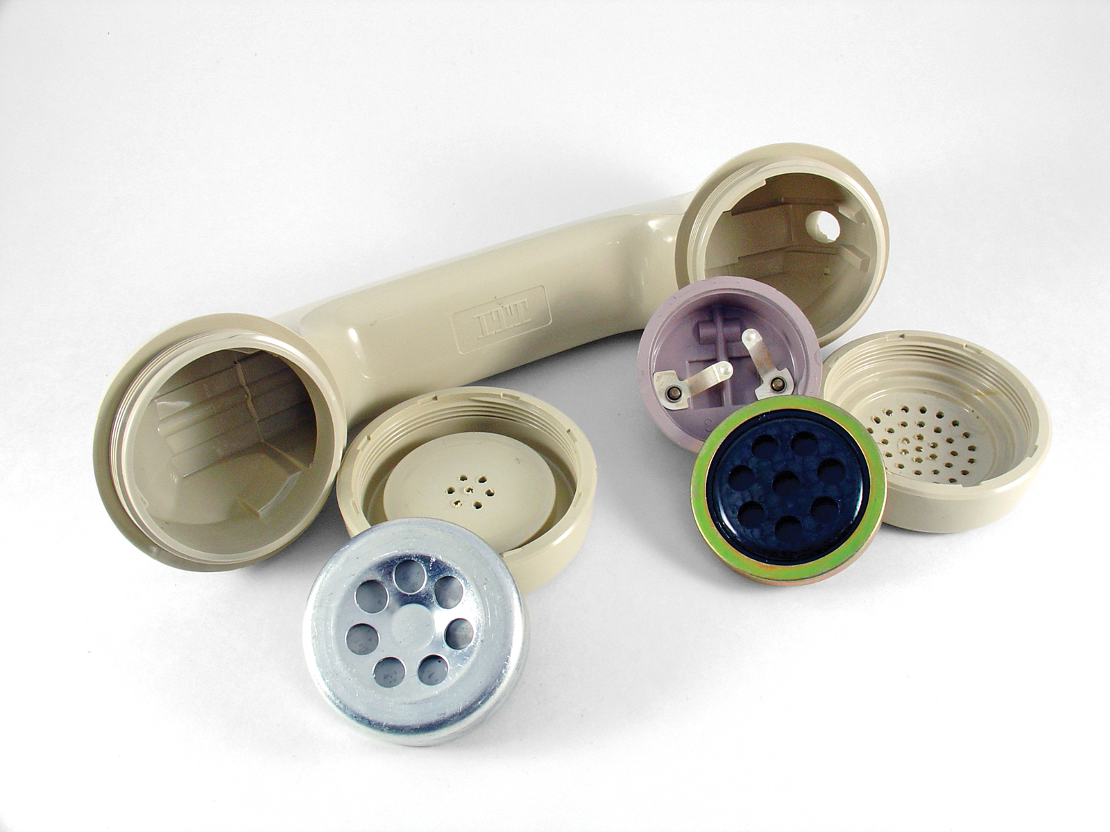
Remove the microphone and speaker from the handset.

Unscrew the handset’s round caps. The microphone is held against spring terminals and tends to jump out, so be careful it doesn’t roll away. The speaker and the plastic microphone holder should pull out easily. Remove all the original wiring from the handset and set it aside.

NOTE: You can reuse the old wiring for the hack, but if you do, make sure to untwist the ends and cut away the flexible cotton fibers inside before you solder, or you’ll end up making a mess.

Install the push button and LED.

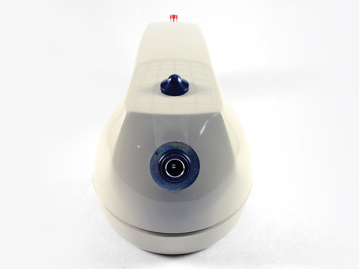
Choose a location for the push button and drill a hole slightly larger than the threads. Solder a few inches of wire to each terminal and install the push button, securing it with the supplied nut. My headset had a micro switch in the center of the PCB to answer calls and toggle power. Yours will likely have a button somewhere that does the same thing. Desolder the button from the PCB and solder the wires for the new push button in its place. My headset also had volume control buttons, but I left those in place because I can control the volume from my cellphone instead.

To add the LED, drill a hole in the handset just large enough for the LED holder. Solder wires to the legs of the LED and install the LED in the holder. Push the entire assembly into the hole you just drilled — it should be a tight fit. Desolder the surface-mount LED from the headset PCB and carefully solder the 2 wires for the new LED to the exposed pads. The polarity matters, so if the LED fails to light up later when testing the headset, try reversing the wires.

Install the microphone

Attach a few inches of wire to each terminal of the handset speaker and feed them through the handle. Carefully solder the wires to the speaker connections on the headset PCB, using your diagram as a reference.

I was able to get the carbon microphone on the handset to work by adding a 1K series resistor and wiring it to the microphone terminals on the PCB. Without the resistor, my voice was too loud and distorted. You may have to experiment to find a resistor value that works best for you. For better audio quality, you can install an electret microphone (RadioShack #270-092) instead.

Install the charging jack.

Remove the original charging connector from the headset. To find the ground pin, test for continuity between each pin and the negative battery terminal on the PCB. Mount the coaxial power jack on the handset, taking advantage of the round hole left behind by the cord. I added a washer so the jack would fill the relatively large opening. Solder wires from the power jack to the charging terminals on the PCB, making the center pin the positive wire.

Modify the charger.

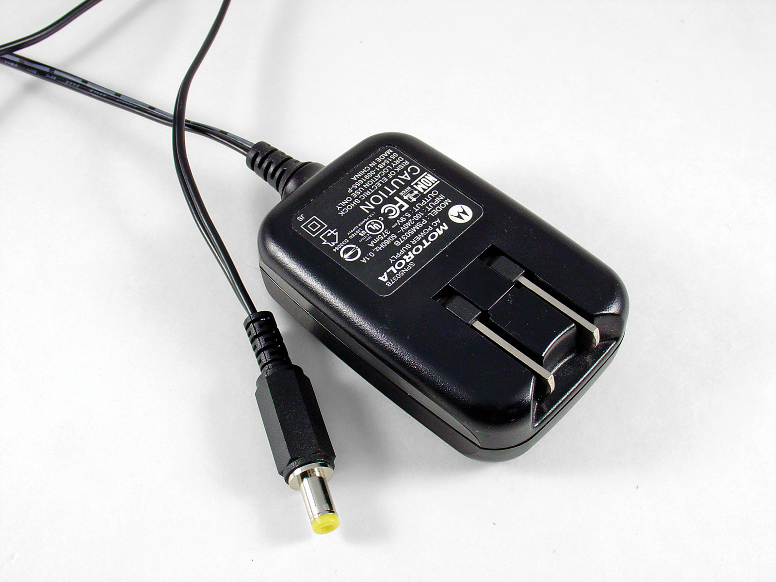
The charger used a proprietary 3-pin connector to connect to the headset, so I cut it off. Only 2 of the pins are actually used for charging, so I replaced the connector with a more common coaxial plug to match the jack on the phone. Plug in the charger and use the multimeter to determine the polarity of the wires. Then connect the positive wire to the center of the plug, and the negative wire to the outside terminal.

Assemble the handset.

Reinstall the headset battery, making sure to solder the wires with the right polarity. Use hot glue to secure the battery to the PCB. Put a dab of hot glue over each wire’s soldered connection to the PCB. This gives the wires some strain relief and keeps them from ripping the traces off the PCB.

Insert the headset PCB into the handset behind the microphone holder. Install the speaker, microphone holder, and microphone. I had to remove a plastic tab from the back of the microphone holder to keep it from hitting the charging jack inside the handset. Screw the caps back onto the handset.

Follow the headset manufacturer’s instructions to turn on your new retro wireless handset and pair it with your cellphone. Call a friend and test it out. If everything works, admire your finished handset.

You’re done!

Conclusion

This project first appeared in MAKE Volume 20, page 151.