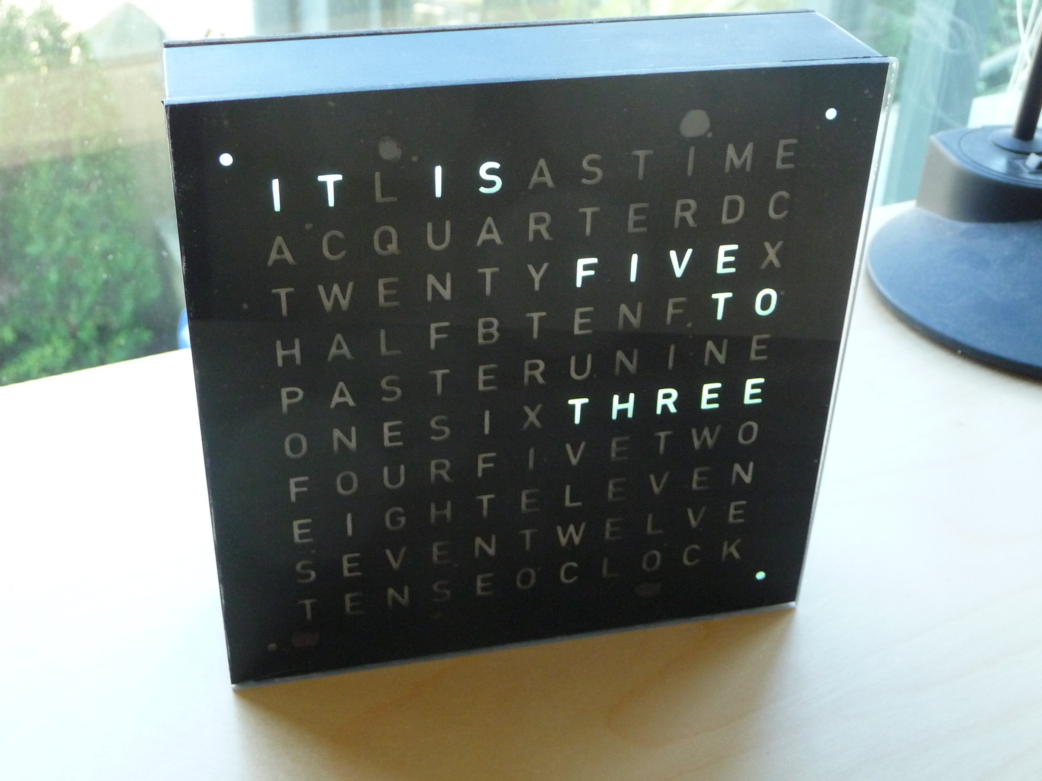
This word clock has a lot of small steps that add up to a moderately difficult build. You’ll be building three circuit boards, possibly making (or modifying) a frame, soldering SMD parts and playing around with finicky die-cut stickers.

However, the end result can be very satisfying. If you’re concerned about doing some of these steps yourself, there are many on-line services that you can use to make your life simpler. The circuit board files can be sent away, the light guide can be laser-cut, and you can probably custom-order a frame to your dimensions from the local art store.

What will the next generation of Make: look like? We’re inviting you to shape the future by investing in Make:. By becoming an investor, you help decide what’s next. The future of Make: is in your hands. Learn More.

Project Steps

Planning

The frame for this project can be anything that you can find, but make sure it is at least an inch deep. This will give you space for the light guide, circuit boards and wire.

The frame needs to have an internal dimension of 6 inches x 6 inches. For my frame, that meant the outside dimension was about 6 1/4 inches square as the aluminium was 1/8 in thick.

The acrylic front piece needs to be cut to the same dimension as your frame. Likewise for the vinyl sticker and the back board.

The back board can be almost any material but it should be a little firm as it will hold 4 buttons and you don’t want it buckling under pressure.

Download the Arduino code, Fritzing and Illustrator files from github.

Prepare the circuit boards

You need to create three different circuit boards – one for the Arduinio, one for the buttons and one for the lights. The PDF and Fritzing files for each circuit board are linked above. The PCB for the lights is the most challenging as it is largish, quite detailed and double-sided.

I won’t describe the full steps for creating the circuit board as there are many excellent tutorials already on the web. I used Colin Cunningham’s YouTube video for my inspiration.

The biggest challenge for the double-sided PCB is lining up the two sides of the board prior to exposure. After printing out the templates on transparencies, place double-sided foam tape around three sides (using your PCB as a guide for size). Remove the PCB and line up the two sides. Holding the transparency in place, lift one side of the top transparency, remove the protective strip from the tape and press the transparency in place. Repeat for each corner and you will have a pocket for the circuit board that will keep everything snug when it is being exposed.

Be sure to use two layers of each “negative” – I found the UV light was strong enough that my circuit board was washed out with only one layer.

Drill the circuit boards

Each circuit has several holes to drill, none more so than the light PCB. I used an 0.8mm titanium drill bit as regular bits will not stay sharp drilling into the fibreglass material the PCB is made from.

I was concerned that not having a drill press would lead to poor-quality holes, but the PCB is so thin that it was not a problem to “freehand” the drilling.

Soldering - Part 1

Starting with the Arduinio board, solder in the header pins, DIP socket and power supply barrel jack. Next, solder the tactile buttons, pull-down resistors and if you like, the hook-up wire.

There are many through-hole vias on the LED PCB. I used leftover wire from snipping off the leads of components from prior projects.

Begin by placing the wire in place and soldering on one side.

Then flip the board over and solder the other side. Now you can snip the excess wire from each side.

Do only one row at a time on each side before flipping it over as it is easy to lose track of what has been soldered and what is still remaining.

Remember that not all the holes require a through-hole via. There are a few header pins, a coin-cell battery holder and some other resistors.

Soldering - Part 2

Soldering the SMD LEDs on to the main PCB was the most intimidating part (at least for me). However, once I got going things went quite smoothly.

Begin by soldering the MAX7219 LED controllers, remembering that many of the pins require contact on both sides (so soldering on both sides of the board is necessary).

To solder the SMD LEDs, apply a very small piece of solder to the pad for the LED. Then, apply some flux to the solder you have just applied to the board. Next, with one hand, use some pliers to put the LED in place and then touch the soldering iron to the pad very briefly. Repeat 113 more times.

Solder the capacitors (the big one has polarity – so double-check that it goes in the right way), resistors and header pins.

The value of the resistor is very importantsee this page for information on how to calculate the value appropriate for the LEDs you are using.

Soldering - Part 3

Soldering the DS3231 is also a little tricky – see this YouTube clip for tips on how to solder SMD pieces – but with a bit of patience it’s not so bad. Use a similar method to that used for the LEDs.

Place a drop of solder on the board

Apply flux to the solder

Hold the part in place using small pliers while you solder it in place.

Solder any last pieces, including the coin-cell battery holder

Send the code for the Arduino to the device.

There are many tutorials for completing this step and the Arduino website is a great resource.

Test the circuits

Connect the circuits and test the device. I found I had a few bad solder connections, and a few scratches had broken my traces so I had to apply some solder to repair those points.

You may also find an LED is not working correctly – check the connections first, and then try replacing the LED. I had at least one that was defective.

Light guides

Using a utility knife, cut strips of cardboard about 1cm wide and at least 6 ½ inches long. You will need about 20 of these.

Next, place a guide on the east-west axis and mark off the spaces between the LEDs. Repeat for the north-south axis.

Place 10 pieces together and using a rotary cutter, cut notches half-way down at the points you marked off. Make the notches as wide as the cardboard.

Fit together the pieces of cardboard into a grid. Remember that it is a not a square grid and that the east-west and north-south spacings will be different

Cut the grid to the size of your circuit board and if necessary, sand off the edges so that the edge of the light guide is flush with the edge of your frame.

Prepare the letter stencil

I went to a local commercial printer to get the vinyl sticker die-cut. The Illustrator file is attached above. The sticky side needs to be on the “right” side. When the sticker is applied to the acrylic backing you want to be able to look through the acrylic and be able to read the text normally.

When it comes from the printer, you will have to remove the letters. This is pretty finicky so take your time, use a utility knife to lift the letters out and pliers to hold the internal spaces in place (the gap in the “R”, “A”, and “O” is especially tricky).

After all the letters have been removed, place the backing material (supplied by the printer) on to the letters. This will hold everything in place when it is placed on the acrylic

Apply the letter stencil

Remove the protective paper from the acrylic and lay the piece down on a clean work surface.

Remove the backing from your stencil and carefully line up the edge of your stencil to the edge of the acrylic.

The backing will be slightly sticky – use this to your advantage by pressing it into your work bench. It will keep everything in place while you proceed.

Working very slowly, use a credit card to incrementally apply the stencil to the acrylic. Take your time and work the credit card back and forth to get the smoothest possible finish.

Remove the backing from the stencil and check for any major bubbles. I’ve found that some of the small bubbles will disappear with a bit of vigorous rubbing.

Prepare the frame

Assemble your frame and paint to your desired finish. The frame I used was originally unfinished so I primed the bare metal before spray-painting a flat black finish.

The Arduino PCB has the power supply so it needs to be mounted somewhere sturdy for when the barrel is inserted. I used the edge of the frame and epoxy resin to affix nuts through which the board could be attached.

You might also need to put down a layer of hot glue on the frame to act as an insulator between the bottom of the Arduino PCB and the frame – you could get some short circuits if the two come in contact.

Cut the back board

Using a utility knife, cut the back board to the size of your frame. Line up the power supply and cut the hole for the power supply. You can use a drill to mark the corners which will make things go a little smoother

For the buttons, mark and cut four square holes. It is mostly a matter of aesthetics as to where the buttons go, but be sure to check that the frame is clear of the PCB.

The button PCB might have some raised solder points. To make sure that the buttons are flush, you can scrape away some of the board.

The back board needs to be securely fastened to the frame. As the corners of my frame were steel, I was able to use a rare-earth magnet in each corner. I used hot glue to attach a small piece of metal to the board and quickly held it in place while the glue set.

Attach the acrylic front sheet to the frame

This step will vary somewhat based on the type of frame you have used. If you have used a regular picture frame you can probably skip this step altogether. I used rare-earth magnets to hold the front sheet to the frame.

Create a block of cardboard (I used leftovers from the light guide) to the appropriate height, leaving enough room for a magnet and a small piece of metal. The metal has to be large enough for a strong magnetic pull, but it also has to keep clear of the lettering. Since the front sheet is not that heavy you can probably get away with a piece about the same size as the magnet.

Glue the magnet to the cardboard block with hot glue. Next, place your piece of steel on the magnet. Place a dab of hot glue on the steel and quickly press your front sheet to the frame. After a few moments you can pull the front sheet away and the steel piece should now be in place.

Putting it all together

Begin by hooking up all your electrical connections (see the attached document for guidance) and insert the coin-cell battery in the holder.

Next, place the light guide/grid on the LED circuit board and slide everything into the frame.

Next screw down the Arduino PCB firmly in place.

You will probably need some sort of spacer to keep the LED PCB tight to the front of the frame. Cut a few small squares of foam-core board of cardboard just a bit larger than your gap. Slide these wedges into the space between the frame and the PCB and it should fit snugly.

The buttons can be hot-glued in place, using a piece of cardboard or foam-core board to build it up to the appropriate height.

Attach small plastic bumpers to the bottom of the frame to give it a sturdy base, snap on the front and back panels and the job is almost complete.

Light diffusion

You need to place a film of some sort between the LEDs and the acrylic front sheet. This will ensure that the letters light up from all angles in a smooth and even way.

I experimented with a few things but found a piece of cheap tracing paper works well. Cut a square of material a touch smaller than your front piece. No need to glue it in place as the magnets will do the job for you.

Clock operation

As soon as you plug in the power supply the clock will light up. You may see some lights flashing at first, but this is normal.

The clock has four buttons. Button 1 sets the hour, button 2 sets the minutes, button 3 cycles through the clock modes and button 4 changes the brightness.

The three clock modes are:

The default mode displays the time with each dot in the corner representing a minute increment. In the picture to the left, the time is 10:27.

The next mode displays the time with the corner dots advancing on each second

The next mode displays the seconds.

Conclusion

This Flickr post was my inspiration and was also the basis for the Arduino code used in this project.