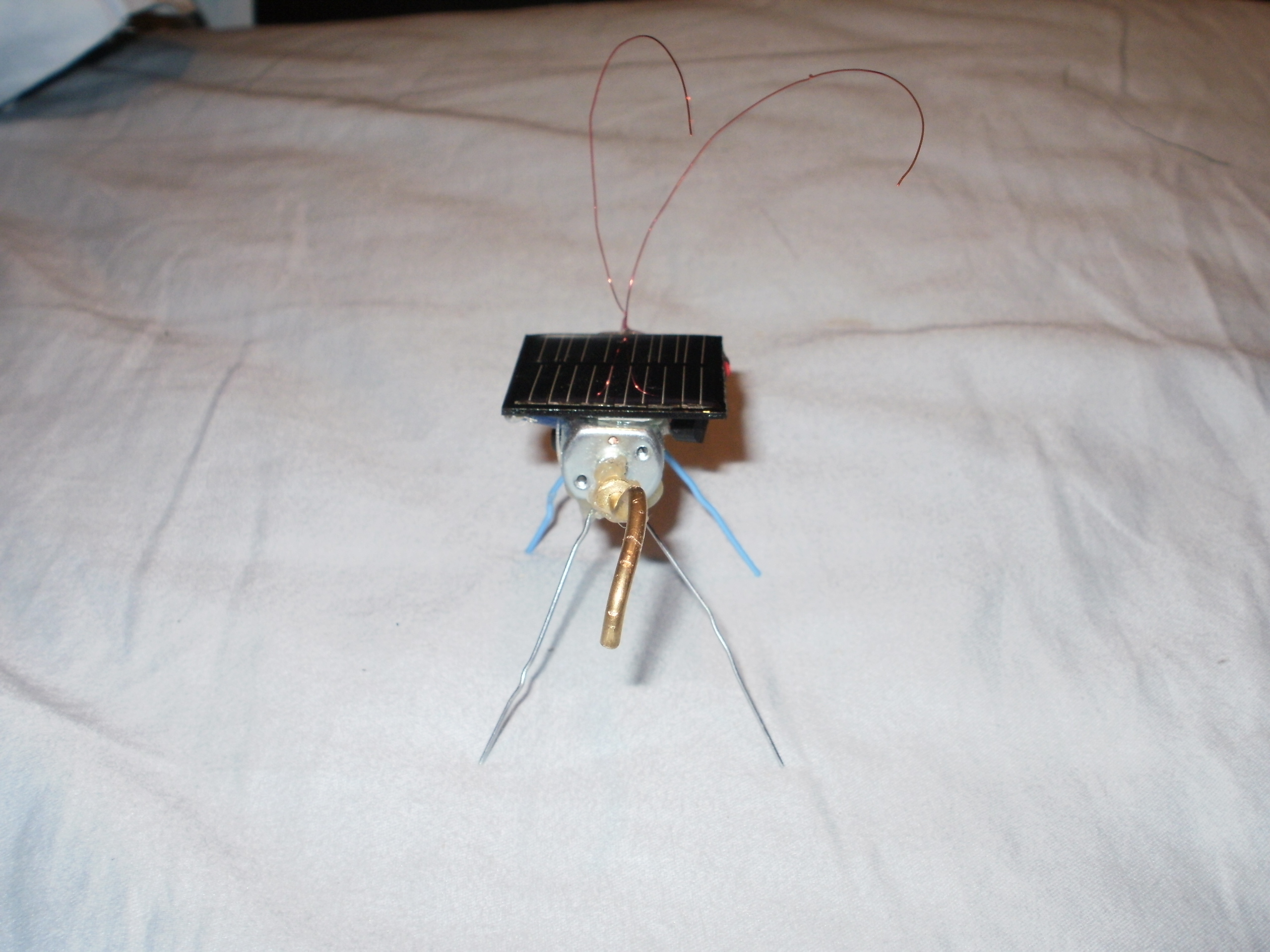
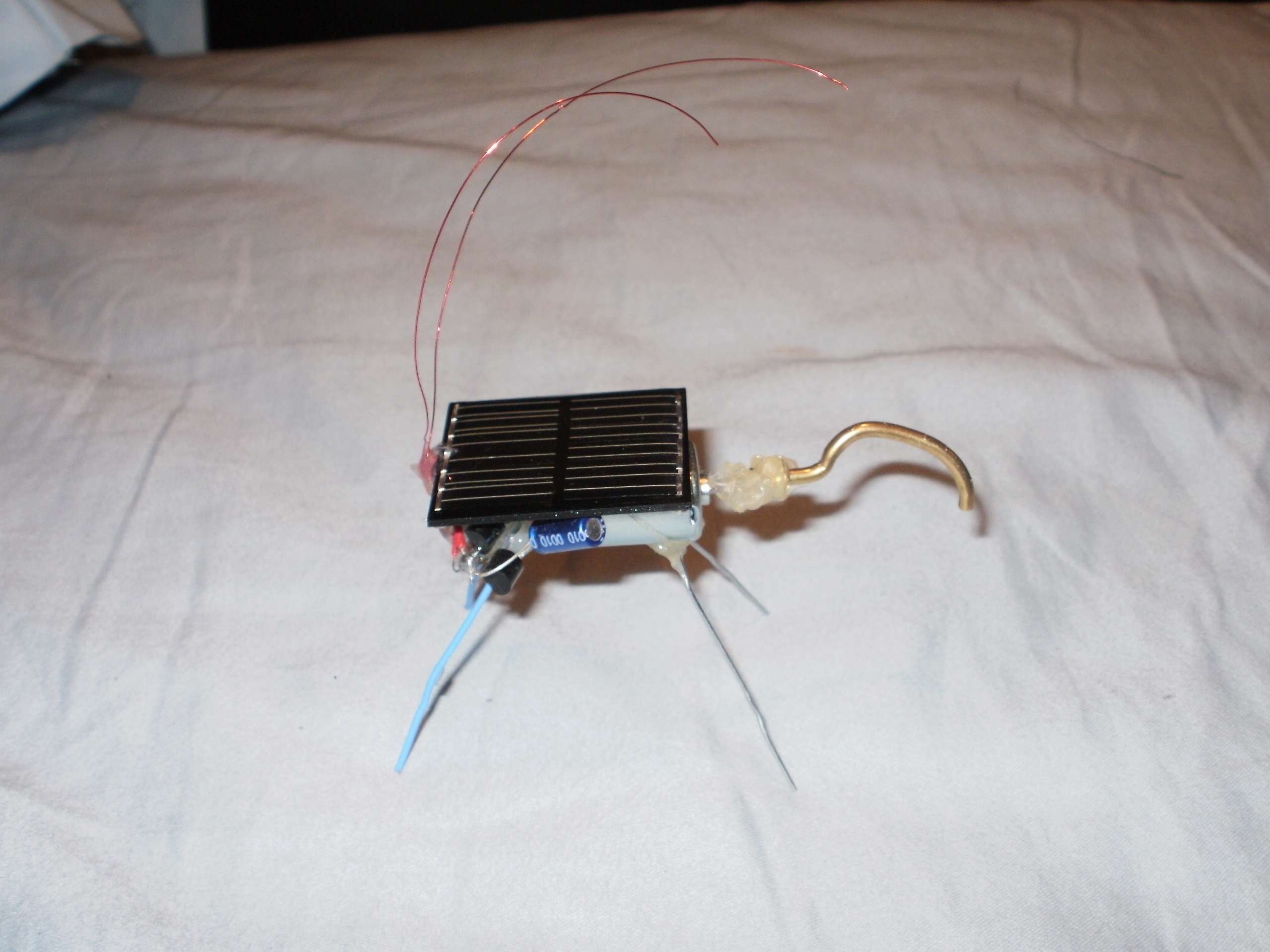
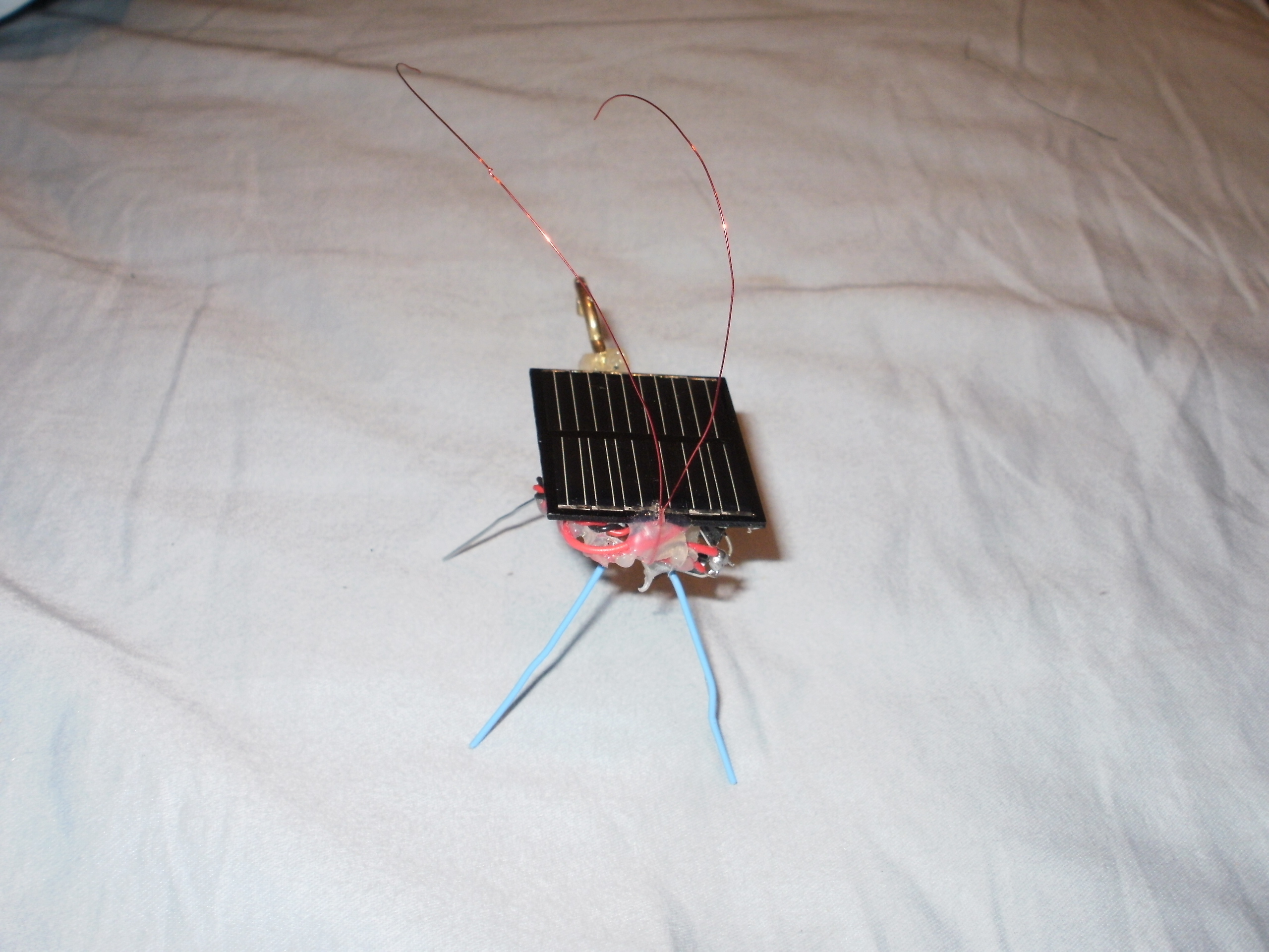
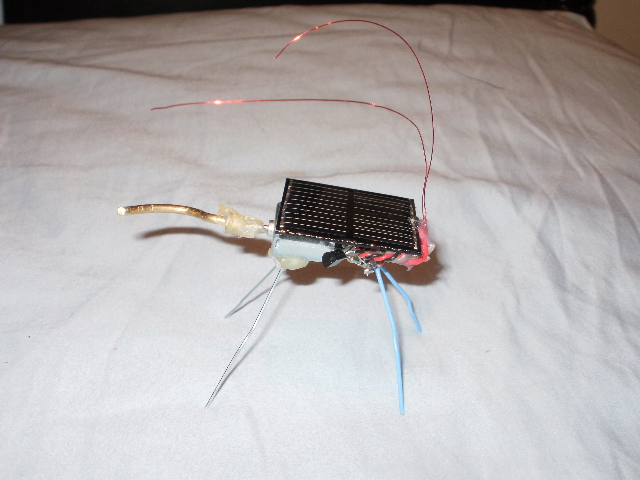
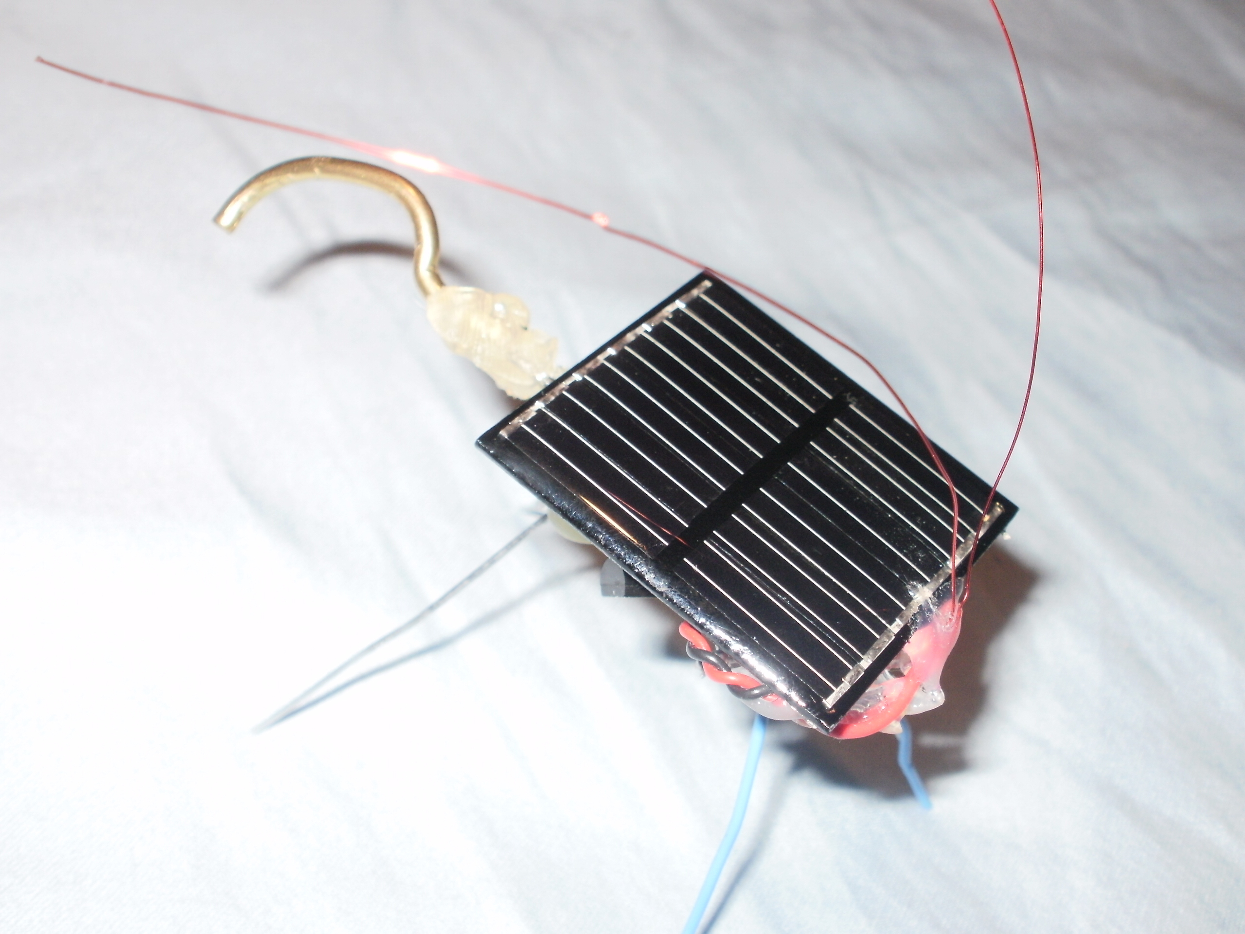
In these instructions, I teach you how to make a vibrating little cute buzzing humming beetle robot. This is great for beginners because of the simple circuit and low parts cost.

What will the next generation of Make: look like? We’re inviting you to shape the future by investing in Make:. By becoming an investor, you help decide what’s next. The future of Make: is in your hands. Learn More.

Project Steps

Building the voltage-triggered Solar Engine control circuit

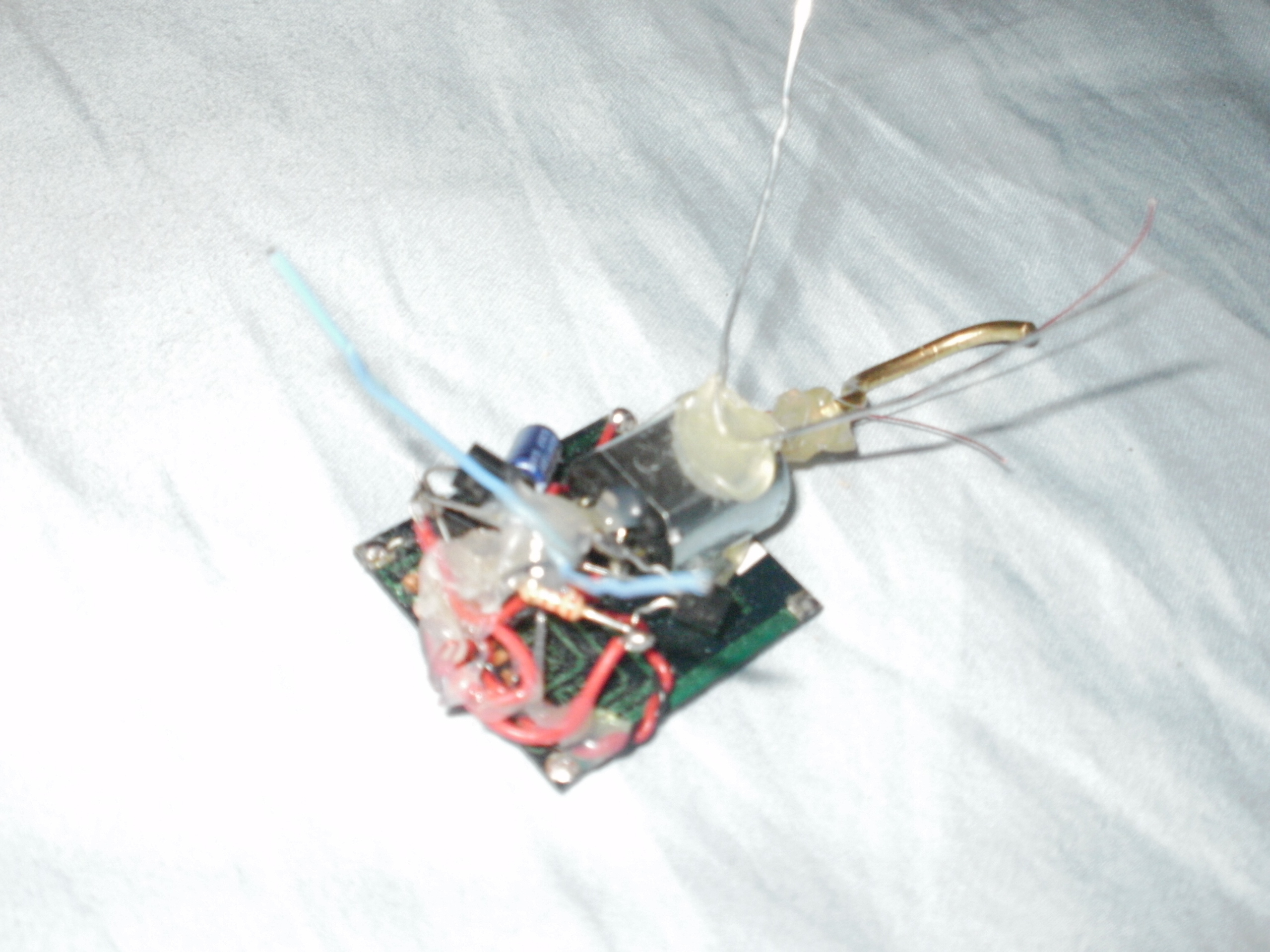
We’ll be freeforming this circuit, which means connecting components together directly, without a board. Parts are easily desoldered and resoldered if there’s a problem.

Face the two transistors up with their pins toward each other. Solder the base pin (middle) of the 3904 transistor to the collector pin of the 3906 (the right pin, as you read the printing).

Use needlenose pliers to gently bend the 3904 emitter pin (left) 90 degrees to the side and its collector (right) 90 degrees up. Bend the 3906 base pin (middle) 90 degrees up and its emitter (left) 90 degrees to the side. Solder the 2.2k resistor from the 3904 collector to the 3906 base.

Trim excess lead length from previous step. Place the 1381 voltage trigger to the right of the 3906, facing the same way. Solder its Pin 3 (right) to the 3904 emitter and its Pin 1 (left) to the 3906 collector. Finally, arc its Pin 2 (middle) around and solder it to the 3906 emitter (left). There’s your basic circuit, ready for motor and power!
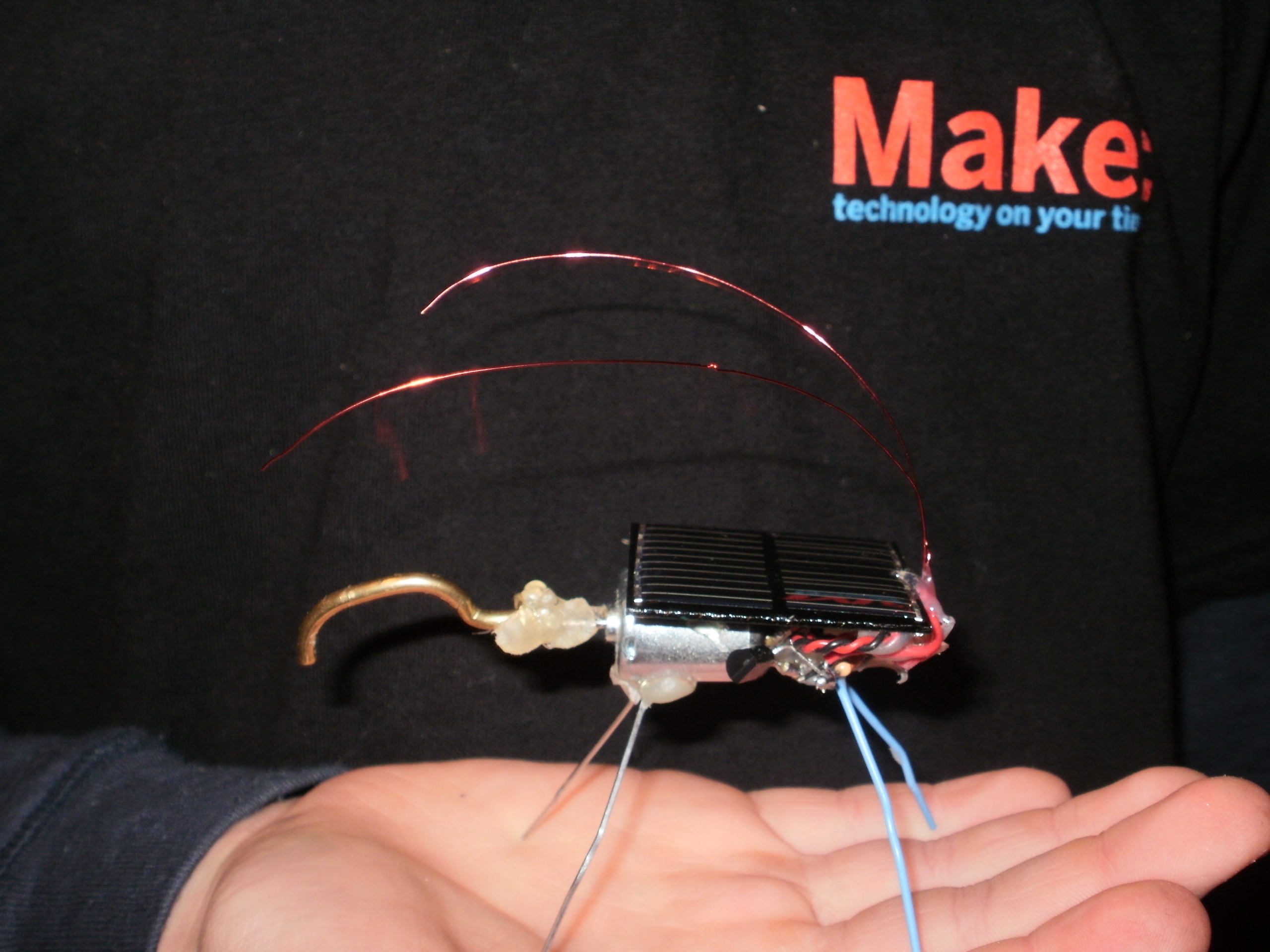
Solder up the electronics

Hot glue the pager motor to the non-light-sensing side. Solder the positive/anode lead of the capacitor to the 3906’s emitter (left) pin. Then solder the capacitor’s negative/cathode to the 3904’s emitter (left) pin. Solder the wires to the solar cell, and then solder the red/positive wire to the cap’s positive lead. Solder the black/negative wire from the solar cell to the cap’s negative wire. Finally, hook up the motor. Solder the red wire to the 3906’s emitter. Then solder the black wire to the 3904 collector (right). Done with that!

Mount the rest of the components

Hot-glue the rest of the components to the other half of the solar cell. Unbend the paper clips so that you just have thin strips of metal. Bend them at the middle, at a 65-degree angle. Hot-glue one to the motor, and the other one to the small electronics. Make sure it looks similar to a vibrobot.

(Optional) Make it cute

Bend a 5″ length of 30-gauge wire in half. Hot glue it to the opposite end where the pager motor is. Hot glue on some google eyes to make it look similar to you. Customize!

Testing your Solar Buzzing Beetle

Now, put the SBB on a flat surface in the sun, or shine a flashlight on the cell. After a little while, the circuit will trigger, the capacitor will dump, and your SBB will take off for a short run. Shine, wait, and repeat.

If your BEAMbot doesn’t make you beam, carefully examine all connections, resolder anything that looks weak, and separate any components that might be touching (shorting). It’s a simple circuit, so not much can go wrong besides incorrect connections or bad joins.

Resources

There are many more hacks and variations on this project as well as other applications for the Solarengine. For more information, see “Getting Started in BEAM,” MAKE, Volume 06, page 57. Schematic for Miller variant of Solarengine circuit: https://makezine.com/06/beambots

I got the idea to make this when I saw the solar grasshopper kit from the Maker Shed. My grandma got me 2 robot kits from the Maker Shed for $69.99 each! (She’s very generous during the holidays.) I thought “Hmmm…”

You can also use an LED in place of the voltage trigger, just search “BEAM solar chariots” and you will find out the circuit there.