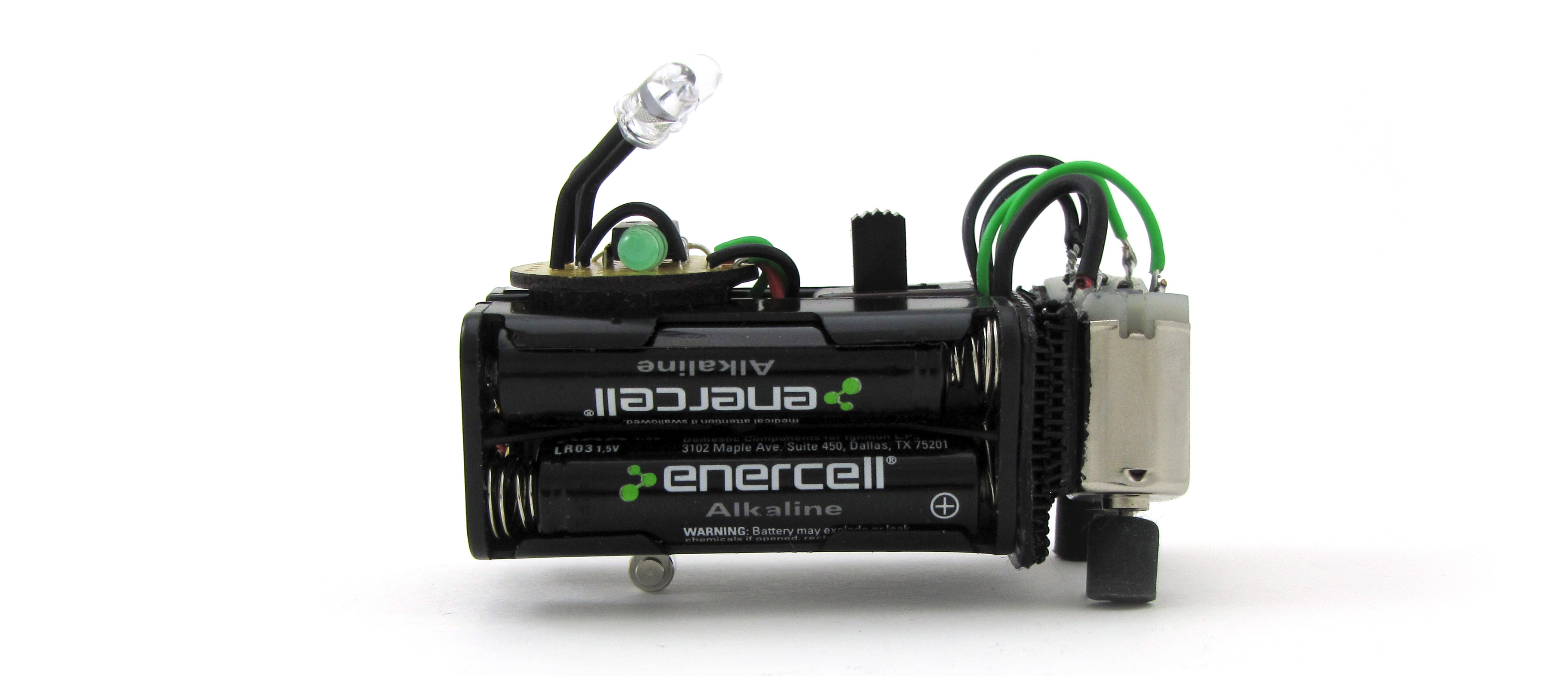
BEAM robotics is a way of thinking about and building robots with roots in the “behaviorist” or “actionist” robotics movement of the 1980s. Rather than relying on microprocessors, programming, and digital logic, BEAM designs favor discrete components, stimulus-response control systems, and analog logic. From a design perspective, BEAM robotics is about getting the most complex and interesting behaviors using the simplest circuits, actuators, and components. Therein lies the challenge.
BEAM is an acronym for:
- Biology — BEAM robots take inspiration from nature, especially “simple” organisms like plants, worms, and insects. They are often classified by their primary sensor system: audiotropes respond to sound, thermotropes respond to heat, radiotropes respond to radio sources, etc. They can be further subdivided by their type of movement or positioning mechanism: sitters, squirmers, jumpers, fliers, rollers, walkers, and so forth.
- Electronics — BEAM robotics requires clever circuit design. Unlike digital systems where you just have to interconnect all the right pins and make sure their voltages go high and low at the right times, BEAM robots use analog circuits, which are more subtle. Designing digital circuits is more like computer programming, while designing analog circuits is more like plumbing.
- Aesthetics — BEAM robotics is as much art as science. That a design “look cool” is not always a priority for engineers, but the BEAM approach emphasizes the importance of looks, though not just for their own sake. Rather, polished aesthetics are a test that mature BEAM designs should pass. A good-looking robot has been designed and constructed with close attention to detail. Its form is a refined, efficient, natural, logical reflection of its function. People who see it will recognize its beauty and want to preserve it, so aesthetics becomes a “survival” function, as well.
- Mechanics — Sometimes a mechanical solution is cheaper, easier, or more robust than an electronic one. For example, rather than complicate a circuit with electronic motor controls, BEAM designs often adopt simple mechanical “hacks” (like steeply tilting the motors or using small-diameter wheels) to regulate motor speed.
The SunBEAM Seeker is a very simple phototrope (meaning it responds to light) based on Randy Sargent’s classic “Herbie” design, which he originally developed for a line-following competition at the Seattle Robotics Society’s 1996 “Robothon” event. Using as few as six components, the “Herbie” circuit produces a robot that will follow a black line traced on a white floor or, with the photosensors pointing upward as in this version, seek out the brightest light source in a room.
We published a more complex version of the Herbie design as Mousey the Junkbot back in MAKE Volume 02. To the basic design, Mousey adds a pushbutton “bump” switch and a relay that temporarily reverses the motors so that, on running into something, the robot will back up for a few moments before it begins steering toward the light again, hopefully clearing whatever obstacle it ran into during the next attempt.
The SunBEAM Seeker borrows the LED “pilot light” and current-limiting resistor from the Mousey design, but uses IR phototransistors instead of diodes. It also adds a roller lever limit switch that serves as a tail-wheel so the bot will automatically turn on when you set it down, and off when you pick it up again (or if it flips over).
How It Works
The core of the “Herbie” circuit is the LM386 power amplifier chip. To simplify a bit, we can think of the chip as a “black box” with inputs and outputs that respond in predictable ways, and don’t have to completely understand what’s going on inside.
First, on the input side, there are pins 2 and 3. Basically, the chip is constantly comparing the voltages on these two pins, and responding to the difference between them. Since we’ve connected light sensors to pins 2 and 3, the chip is responding to the difference in light levels detected by these two sensors — i.e. the different brightnesses “perceived” by the robot’s right and left “eyes.”
On the output side, there’s pin 5. When you first look at the circuit, you may be confused about how the two motors, which are connected in series between power and ground, can be independently controlled at all. The key is understanding what’s going on between them, at their shared connection with pin 5. In essence, when one eye is “seeing” a brighter light than the other, pin 5 acts as a current source at a voltage very close to the main power supply voltage. In this case, both terminals of motor M1 are at nearly the same potential, and it does not turn; only motor M2, which is connected between pin 5 and ground, is powered. It’s as if you put a jumper wire between pin 5 and Vcc. In the opposite situation, when the other eye is “seeing” the brighter light, pin 5 acts as a current sink, shunting any positive potential straight to the chip’s ground connection at pin 4. In this case, it’s as if you put a jumper between pin 5 and ground; only M1 is powered, and the current that passes through it then “takes the easy way out” and goes straight to ground, through the chip, instead of passing through M2.


