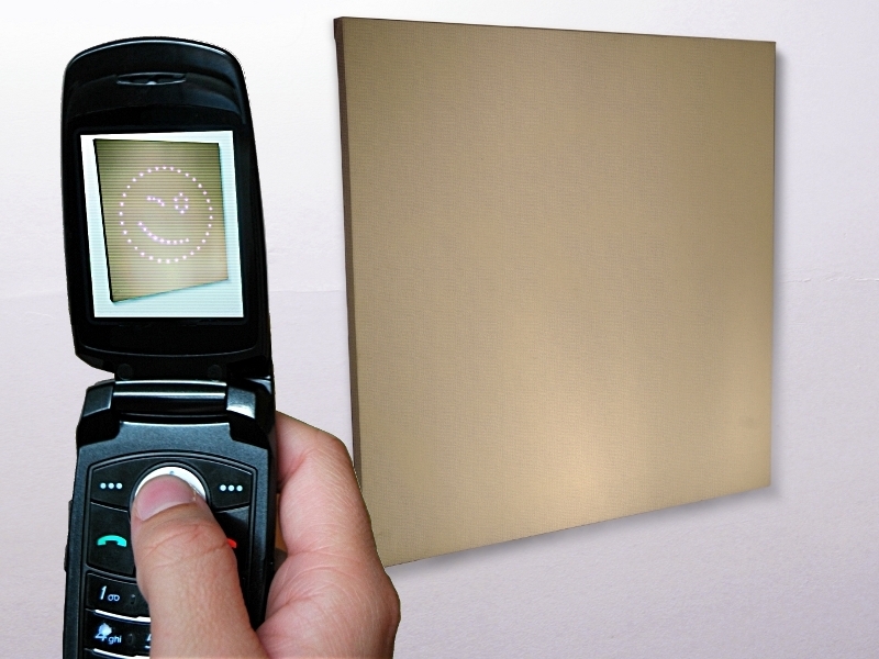
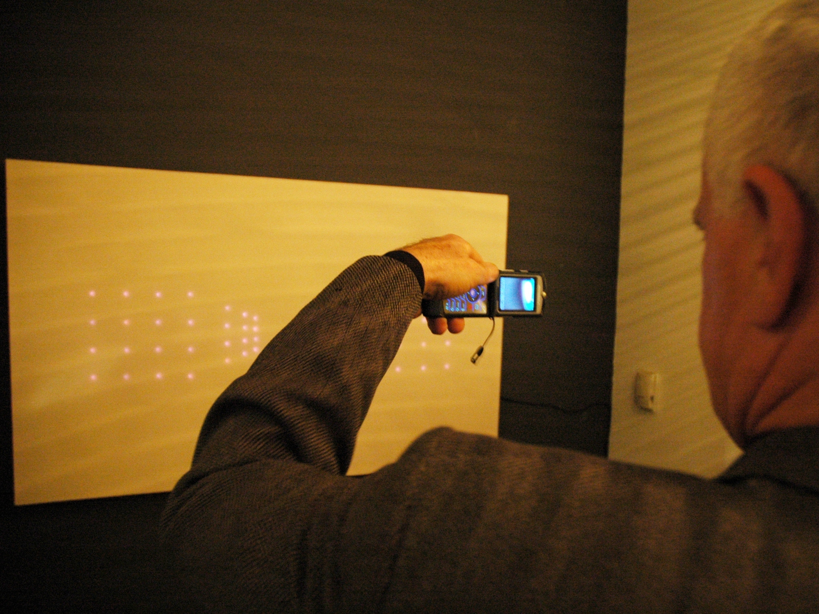
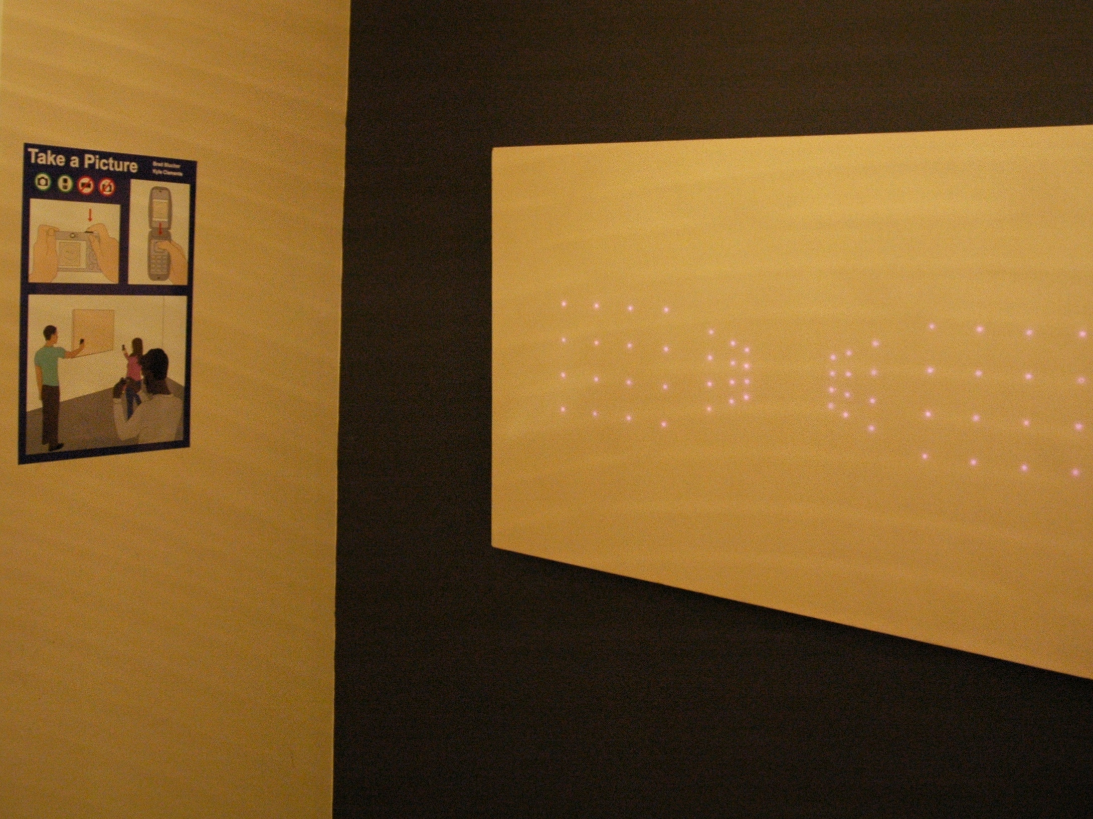
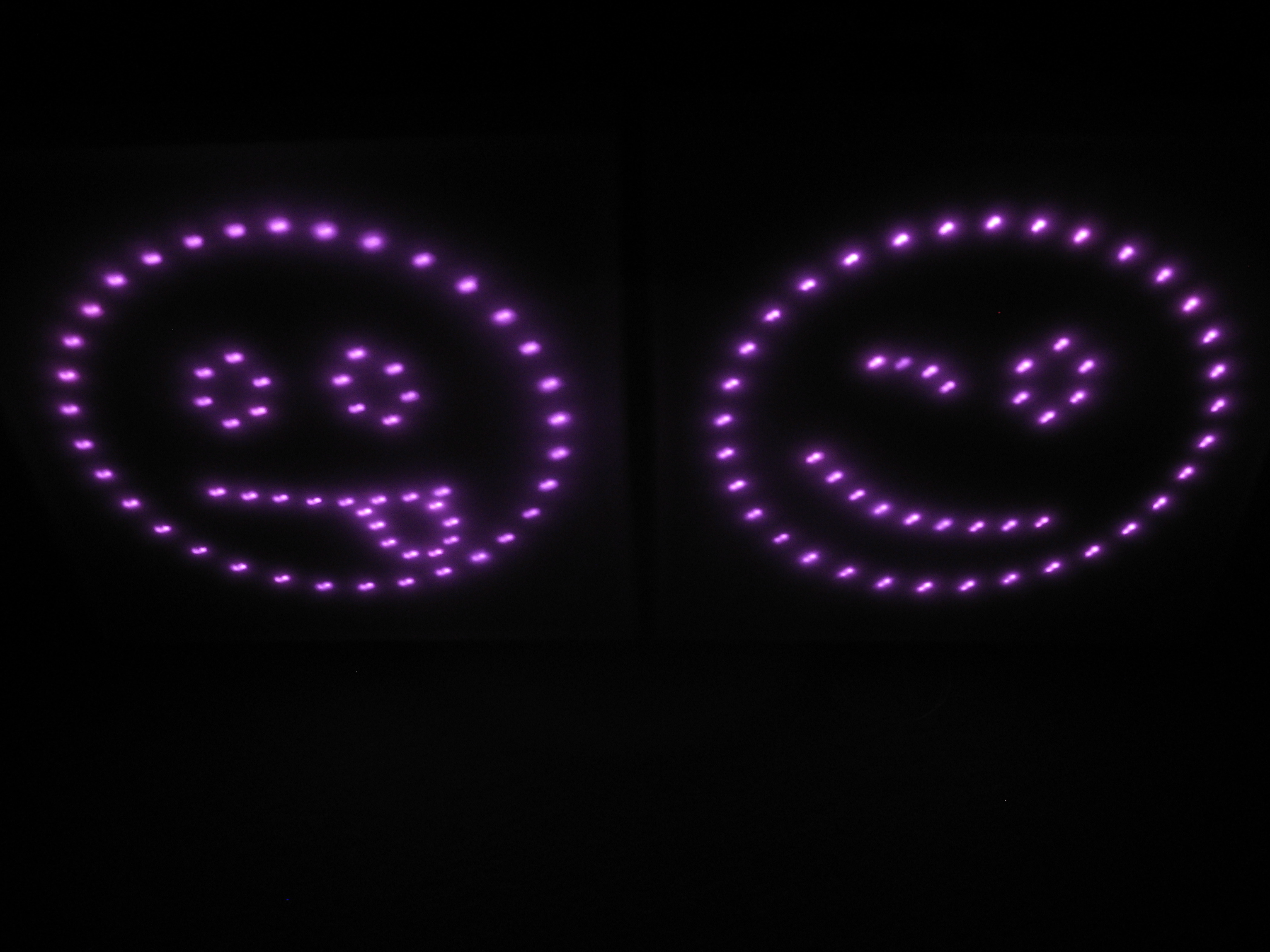
Take a picture is a fine-art project by artists Brad Blucher and Kyle Clements. In the exhibit, the human eye see is only able to see blank surfaces (in our case, blank canvases). People walk up to the show space and see blank canvases hanging on the wall. They see absolutely nothing, then make some nasty comments: “Those lazy, pretentious artists, thinking they can get away with doing absolutely nothing.”

What the audience is unable to see is the hidden maze of wires and circuits. IR LEDs behind the canvas are emitting light that their eyes can’t see, but a digital camera can. Holding a digital camera up to these seemingly blank canvases will reveal hidden images.

This project revolves around one single, extremely simple principle: IR light is visible to digital camera sensors, but invisible to the human eye.

This guide assumes that you are already familiar with woodworking, stretching canvas, designing and etching your own circuit boards, and working with basic electronics. Nothing in this guide is particularly difficult, but it does require a diverse skill set. It’s very good for the jack-of-all-trades-master-of-none type of person.

What will the next generation of Make: look like? We’re inviting you to shape the future by investing in Make:. By becoming an investor, you help decide what’s next. The future of Make: is in your hands. Learn More.

Project Steps

Make sure you know enough people with digital cameras to make doing this project worthwhile.

Gather up several 1″X 1″ and 1″X 3″ pieces of wood (I used clear white pine), and a large piece of Masonite.

Gather up your soldering stuff (soldering station, side cutters, wire strippers, solder, reverse tweezers, shrink tubing, etc.).

Get your do-it-yourself circuit board etching stuff (large glass trays, ferric chloride acid, gloves, copper etching board, goggles, laser printer, photo-paper, rotary tool, 1/16″ and 1/32″ drill bits, hacksaw, knife).

Get your wood working stuff out (a mitre saw, a staple gun, a drill, a roll of 20-gauge speaker wire, clamps).

Pick up a bunch of IR LEDs and resistors. The exact number depends on the complexity of your design.

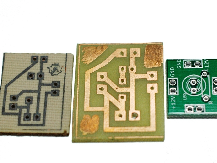
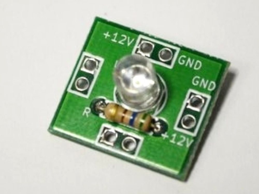
Design, test, and manufacture circuit boards for each LED. Each circuit contains a single resistor, an LED, and some pads for linking the boards together.

We ridiculously over-engineered these boards for flexibility, long-term durability, and re-use.

Eventually, we got lazy and just had our boards manufactured overseas. After doing a thousand iron-on toner transfers, it was time to let someone else do the rest.

I don’t have the original image file for the circuit we used; sorry!

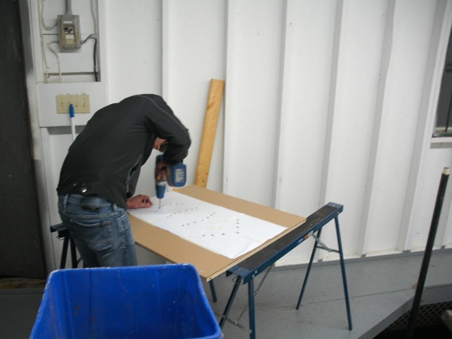
Draw your design on a piece of paper, then tape the paper to a sheet of Masonite.

Find a drill bit that is slightly larger than your LEDs. Callipers would have been a good idea, but we just eye-balled it.

Drill holes through the paper/masonite. Make sure the holes are at least an inch apart, so there is enough room for the circuit boards to fit.

Keep the image centred. You will need to keep a 2-inch strip along each of the edges clear.

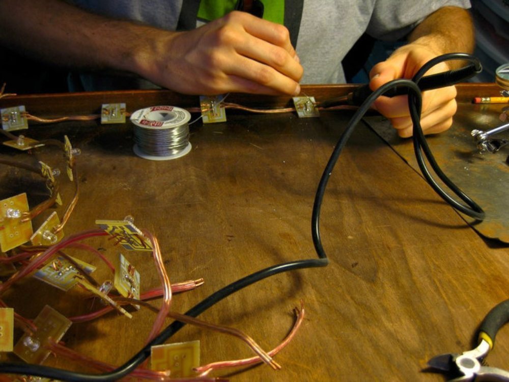
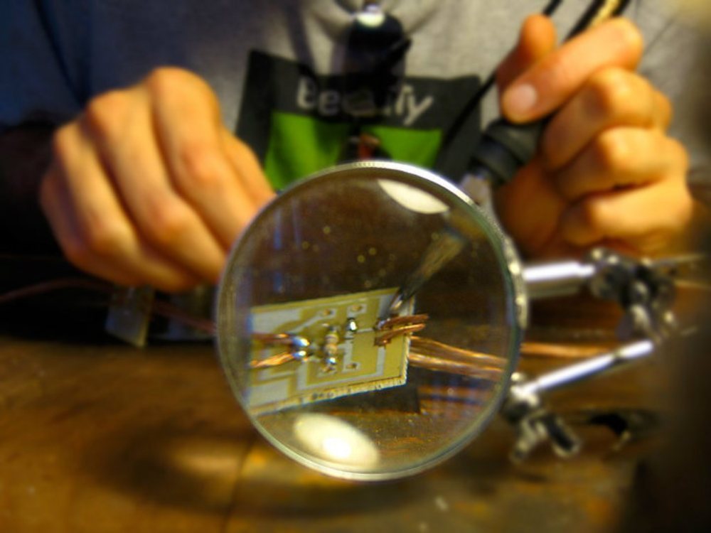
Insert and solder the components into the boards.

If you wish to power these with 9 volts, use 390 ohm resistors (orange white brown) for the IR LEDs.

If you are powering these with 12 volts, use 560 ohms (green blue brown)

To have the LED fit snugly against the Masonite, we put the LED on one side, and the resistor on the other (the image shown here is one we did the wrong way — this LED kept popping out)

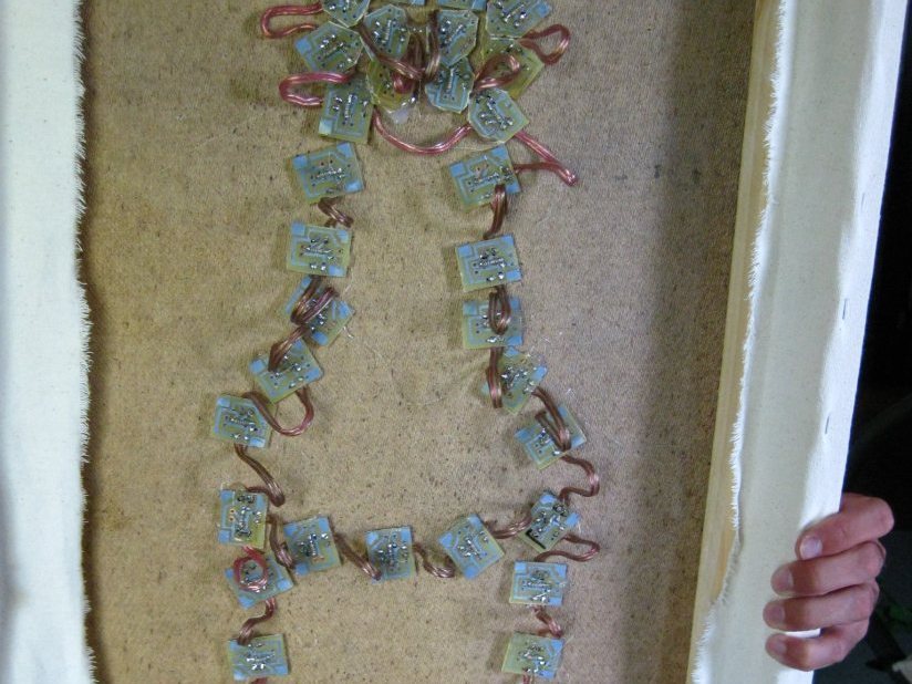
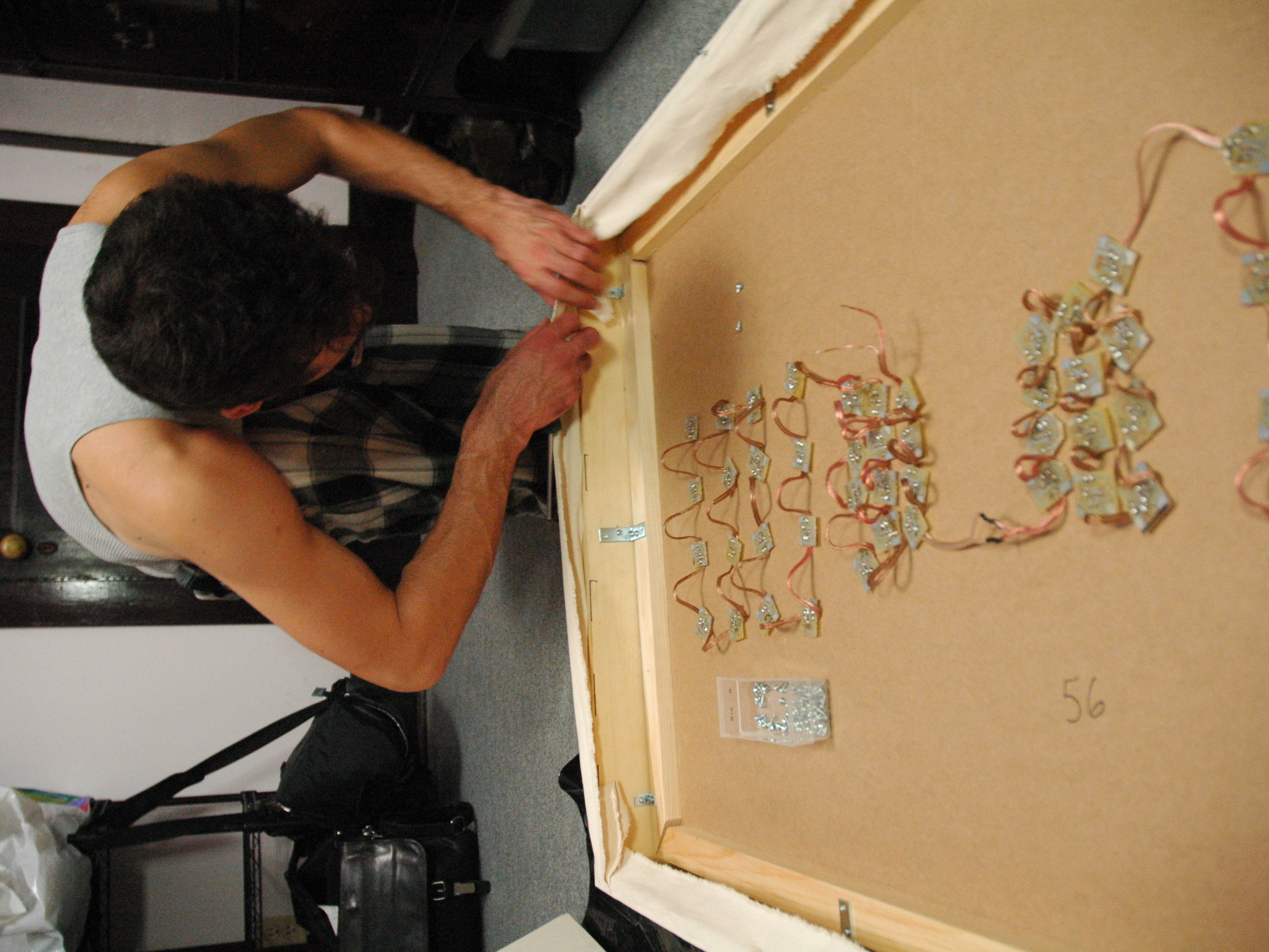
Chain the circuits together with speaker wire (something in the 18-22 gauge range should do it).

Pop the circuits through the holes in the Masonite.

Sometimes, you get lucky and a friction fit is all it takes. Otherwise, break out the hot-glue gun and prepare for 30 minutes of monotony.

Use 1″ X 1″ strips of wood to build a frame to support the Masonite and prevent warping. This frame should be the same size as the Masonite.

Screw this frame to the back of the Masonite sheet.

Use 1″ X 3″ strips of wood to build another frame. This frame is called a stretcher. This is for the canvas to go over.

The Masonite has to fit inside the stretcher, so make the stretcher about 2″ larger than the Masonite.

Use angle brackets to screw the Masonite into the stretcher.

Count the number of circuits in your image. Multiply that number by 20. That’s how much power (in mA) your invisible painting will require. Get an adaptor that can handle that much. eg. 25 LEDs requires a 500mA supply, while 100 LEDs requires a 2 amp power supply. It is safe to use a larger power supply, but don’t use a smaller supply (eg. you can use a 2amp supply for 25 LEDs, but dont use a 500mA supply for 100 LEDs)

Connect the power adaptor to one of the circuit boards, and plug it in.

Pull out your camera and test it out!

Find a place where people are very likely to bring a digital camera, and set up your invisible paintings.

Avoid bright, direct lights (especially halogen) as they can easily overpower these invisible images.

Make instructions, ’cause sometimes, titling the series “Take a Picture” isn’t enough of a hint to let people know they should be taking pictures of the blank canvas. I wish I was being snarky or using some dry wit here, but I’m serious. You will be surprised by how many people just don’t get it.

Conclusion

This project requires you to know a little bit about a lot of different skills. It's the result of combining some very simple things into something entirely unique.

It requires some basic wordworking, but nothing too advanced or difficult. It requires some basic electronics, but nothing too technical. It requires etching skills (OK; this part can be a bit tricky or dangerous). And lastly, it requires some art/design skills.

Good luck!