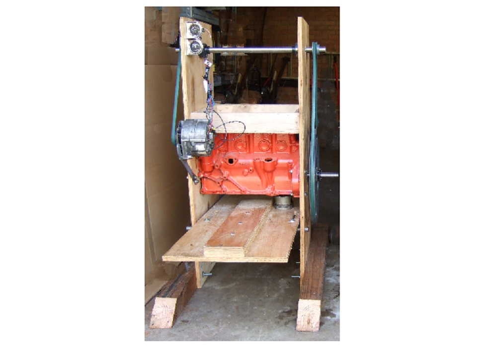
The “Genny” is a multi-purpose treadle-powered machine for rural areas of developing countries, a power source for such needs as:

  • Charging cellphones
  • Charging batteries
  • Processing grain
  • Providing peak power for undersized solar systems
  • Turning water pumps and machine tools

Local – Not Imported

Gennies can be built using locally available materials, tools, and skills.

Their treadle power could be generated by local students in return for much-needed money for school uniforms and fees.

What will the next generation of Make: look like? We’re inviting you to shape the future by investing in Make:. By becoming an investor, you help decide what’s next. The future of Make: is in your hands. Learn More.

Project Steps

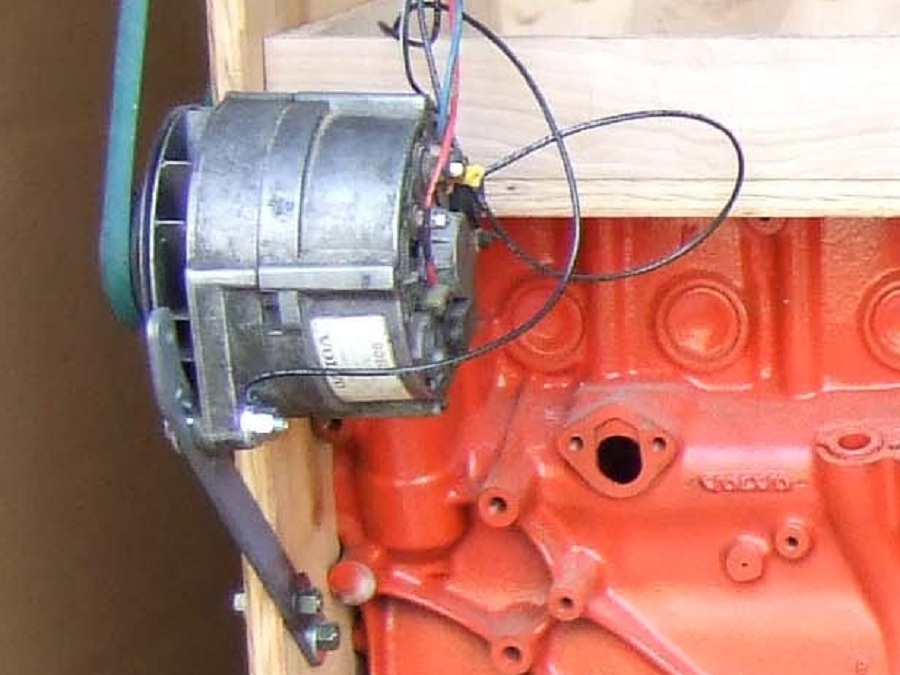
Vehicle alternators are an inefficient power source but may be the only affordable way of generating electrical power in some parts of the world.

The problem is to make a treadle mechanism that will withstand the use (or abuse) of the 4 to 6 treadlers that are needed to make the alternator a practical power source.

My solution is to use an otherwise useless engine block and crankshaft that was originally designed to withstand much more horse power than people can provide..

The Genny design came about from a question from a Peace Corps volunteer at Maker Faire Africa in 2009.

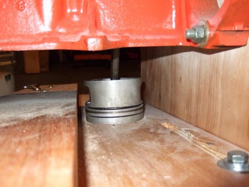
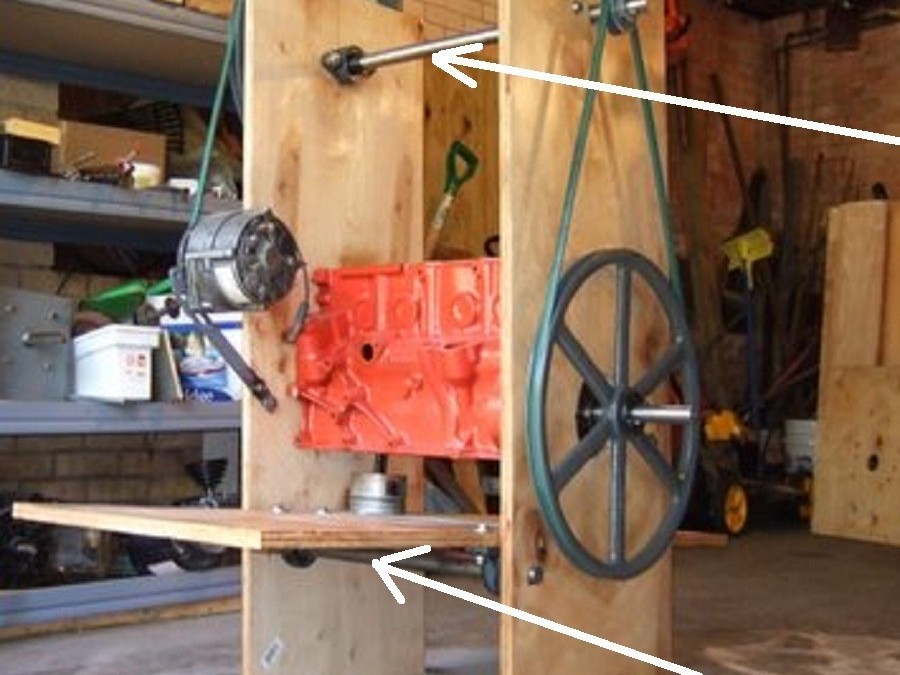
The big Genny secret! The piston and connecting rod come out the bottom of the engine block so that it can be the major part of an almost unbreakable multi-person treadle drive. A vehicle alternator requires much more power than one person can provide.

Using 2 pistons and rods may seem stronger but they are hard to set up and keep in exactly the same plane. If they are not perfectly parallel, most pedaling effort is wasted.

The connecting rod should be extended by cutting and welding a pipe spacer between the 2 pieces. The bores for the crankshaft and the piston pin must be kept EXACTLY parallel. Attaching the piston to the treadle by just threading the top of the piston for hold down bolts is not adequate, this spacer will make room for additional support. A good way to attach the piston is shown in the next step.

The treadle board and frame should be made from pallet wood or something of similar strength.

Very carefully drill and tap the main and rod bearing caps for grease fittings and keep well greased. Countersink the inner side of the bearing caps to remove burrs.

Drill matching holes in the bearing inserts and be very careful to remove any burrs. A grinder may be the best way to cut the holes since the thin insert will be less likely to be bent.

In case a part of the block gets in the way of the rod, break the offending part off. Use a narrow, sharp chisel to make a line of sewing like stitch cuts along the desired break line and then use a big hammer and chisel to break it off.

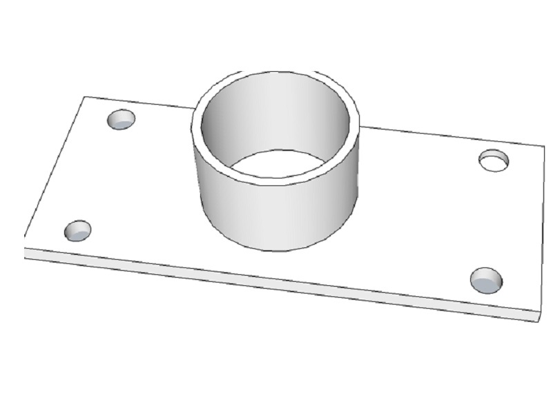
A welded socket is a good way to fix the one weak spot in the system, the piston attachment point. An oversized piece of pipe should be split and then bent to a snug fit on the piston before it is welded to the base plate.

Radial holes should be cut into the pipe and large nuts welded over them to hold clamp bolts. Matching holes in the piston should be drilled.

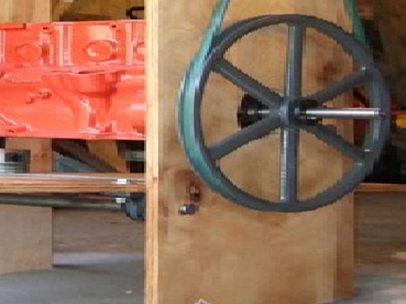
Iron pulleys are fine for proof-of-concept projects like this but are not low-budget solutions.

Probably the only practical pulleys are those that are laminated from wood.

Large wooden pulleys will have to be carefully balanced.

The hub and shaft could be a welded assembly or possibly cut from a piece of another crankshaft.

The belt will probably slip on the small pulley if you don’t use an auto belt idler to get the best “wrap” around it.

It may be necessary to mount another idler centered between the pulleys to use as a belt tension adjuster.

A good choice for the belt could be automotive serpentine type. It sould be tested to which side of the belt would work best.

Pieces of auto drive shaft could be used if large bearings were cast from piston metal.

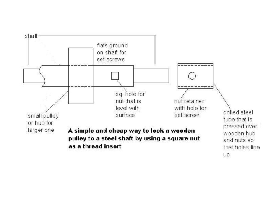
Attaching a wooden pulley to a steel shaft is difficult. The drawing (to be replaced) shows a way of connecting the two. Square steel nuts are fitted into square holes that are cut into the hub and a steel pipe is pressed or driven over the hub and nuts to hold the nuts in place when the set screws are tightened.

Looks like a simple solution but took a lot of thought!

It would be very appreciated if someone would volunteer to re-draw this in a 3D program.

Modestly speaking, I love this! I think it is a unique (at least to me!) solution to a VERY old problem.

There can be no one solution to the alternator problem since so many different kinds are available.

The internal regulator needs to be by-passed and a small resistor put in series with the alternator field coils to reduce the effort needed to get the thing charging at treadle horse power instead of engine horse power.

Resources you really need to study: http://concretelathe.wikispaces.com/Genn… I don’t know where these files come from and if anyone wants them taken down, just let me know.