The Smart Greenhouse is based on the vision of a greenhouse that would not rely on any human adjustment while maintaining a perfect micro-climate for a particular crop being cultivated inside. In other words, ideally this greenhouse could be left for a year in any (reasonable) climate and the seeds that were meant to grow would flourish, totally unattended. It would be perfectly tailored to the vegetation inside to maximize its efficiency. Such a greenhouse would require cognitive abilities to sense its surrounding environment and either use or block certain features while it preserves a micro-climate within the walls of the house. Such variables that are most important for crop success are air temperature, soil moisture and humidity level. This particular model greenhouse addresses two of these factors: air temperature and soil moisture. The greenhouse utilizes an Arduino UNO microprocessor and various sensors to control the regulate the levels of these two variables to a desired set of thresholds. These thresholds would of course vary with the type of crops that one would want to grow in the greenhouse. Inside the structure is a Texas Instruments LM 34 sensor which measures air temperature. This sensor informs the Arduino which then controls opening and closing of roof servos to let hot air out and cool air in if overheating. By use of the mechanical roofs the greenhouse can autonomously keep the inside temperature to a desired level assuming this level is somewhat within the range of the surrounding environment naturally. Additionally, The Smart Greenhouse has an irrigation system triggered by a timer function in the code that can be varied in frequency depending on a plants optimal watering cycle. The timer activates the internal drip irrigation via a servo controlled valve. A possible addition to the Smart Greenhousw would be a soil moisture sensor that varies in resistance with moisture. This sensor could inform the drip irrigation when the soil is too dry thus creating a need based watering pattern, potentially conserving water.

All these features make The Smart Greenhouse one of the most intelligent of its kind (and cost). There is still possibilities for other additions to this system for improving its versatility and efficiency.

What will the next generation of Make: look like? We’re inviting you to shape the future by investing in Make:. By becoming an investor, you help decide what’s next. The future of Make: is in your hands. Learn More.

Project Steps

First step is to build the model greenhouse:

Go to this link for the Adobe Illustrator template files for the pieces:

https://docs.google.com/folder/d/0B8kXmi…

Using laser cutter, cut out pieces from 1/8in thick acrylic.

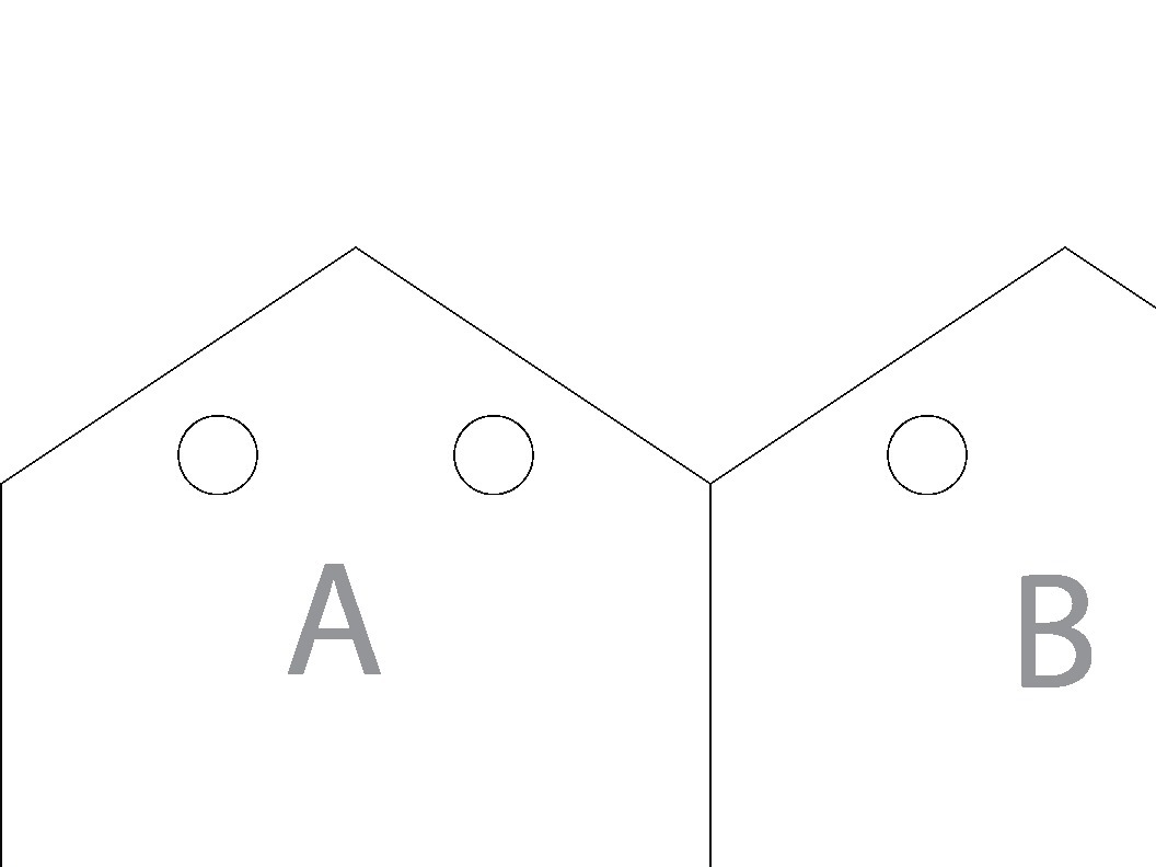
Label the pieces with the letters shown in the Illustrator files.

Assemble greenhouse using labeled pieces and picture at right as a guide.

Use Weld-on acrylic cement to attach pieces together.

For best results use a plywood jig for cementing right angles and apply pressure for up to four minutes while cement sets.

Attach a Parallax servo to each to each roof panel with hot glue.

Using L-bracket, attach the servo and roof panel to the front wall of the greenhouse with hot glue as shown.

Assemble irrigation system as shown:

Hot glue servo to valve handle.

Hot glue servo to greenhouse using wood spacers if necessary.

Using exacto knife, pierce the flexible tuning every inch for the section that lays on the soil in the greenhouse.

This will create a drip irrigation system.

Create water tank by drilling hole in bottom of yogurt container and making water-tight attachment to tubing that goes to input of servo valve.

Use second yogurt container to elevate the water tank.

Now that all the hardware has been constructed it is time for electronics!

Prepare the Arduino and breadboard as shown in the diagram.

Connect Red jumper cable from 5v on Arduino to Red power rail on breadboard.

Connect black jumper cable from GND on Arduino to Black power rail on breadboard.

Attach LM-34 Sensor to PWM extension cable.

Note that the flat side of the LM-34 sensor is facing UP.

Now, Ground is the black wire, Analog Out is the red wire, and +5v is the white wire on the PWM extension.

Wire sensor to breadboard and from breadboard to Arduino as shown in diagram.

Be sure that the black wire from the PWM gets wired to GND, the white wire to 5v and the red wire to Analog 2 (A2).

Thread the PWM with sensor through one of the access portals (round holes) on the front of the greenhouse and have the senor hang in the center of the greenhouse about 3 in from the ground.

Wire the two roof servos as shown in diagram.

Be sure that the right roof servo goes to Digital 9 and the left roof servo goes to Digital 10 on the Arduino.

Wire the water valve servo as shown.

Make sure that the white wire from the servo gets connected to Digital Output 9 (D11) on the Arduino.

Go here to retrieve the Arduino code for downloading to the Arduino Uno board:

https://docs.google.com/folder/d/0B8kXmi…

Open the .ino file in Arduino coding platfrom (if not downloaded, get it here: http://www.arduino.cc/en/Main/Software)

Make sure Ardnuino Uno is selected under: Tools>Board.

Make sure correct serial port selected for USB you will use to connect to Arduino in Tools>Serial Port.

Download code to board using screenshots for guidance if necessary.

Feel free to edit code for personal use. Specifically you may want to play around with the desiredTemp variable and the watering cycle timer for the values that would be ideal for your greenhouse needs!

Your greehouse should be all set to self regulate.

From here, make any tweaks, additions, improvements, etc that you see fit and post them to this article!

Happy farming!