By Sean M. Montgomery and Ira M. Laefsky

Excerpted from a Primer on Biosensing in MAKE Volume 26.

When you experience an arousing stimulus, like an evocative question, a startling noise, or even a disturbing thought, your body generates a variety of psychophysical responses.

One of these is micro-pulses of sweat released after a 1- to 2-second delay from apocrine sweat glands that are tied to the arousal systems in your body via adrenaline and other hormones. The reason your palms might get sweaty during public speaking or a job interview, for example, is because your mind is on high alert and every small stimulus generates one of these pulses.

Each pulse of sweat increases the electrical conductance of your skin, and when this conductance is measured and tied to arousing stimuli, it’s referred to as galvanic skin response (GSR). The Truth Meter measures GSR for display on an LED or for input to a microcontroller. It’s called a Truth Meter because GSR is an important component of lie detector (polygraph) tests used to assess how nervous subjects are while answering questions during interrogation.

So how do we measure GSR? The first step is to understand the signal. With each pulse of sweat, skin resistance decreases suddenly and creeps slowly back up as the sweat evaporates. The Truth Meter circuit transforms this pattern of drops and slow recoveries into sharp spikes deviating from a steady baseline, to light an output LED or trigger some other action.

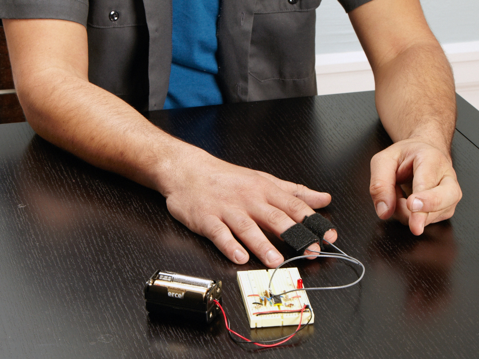
The resistance sensor itself is simply 2 metal cuffs attached around your fingers with a piece of velcro. Hypoallergenic metals used in jewelry and those less reactive with skin, such as stainless steel, are the best, but any solderable metal will work. We recommend copper or brass foil. Fingers are a good place for measuring GSR because apocrine sweat glands occur in very high concentrations on fingers and palms.

YouTube player

What will the next generation of Make: look like? We’re inviting you to shape the future by investing in Make:. By becoming an investor, you help decide what’s next. The future of Make: is in your hands. Learn More.

Project Steps

Make the 2 sensors.

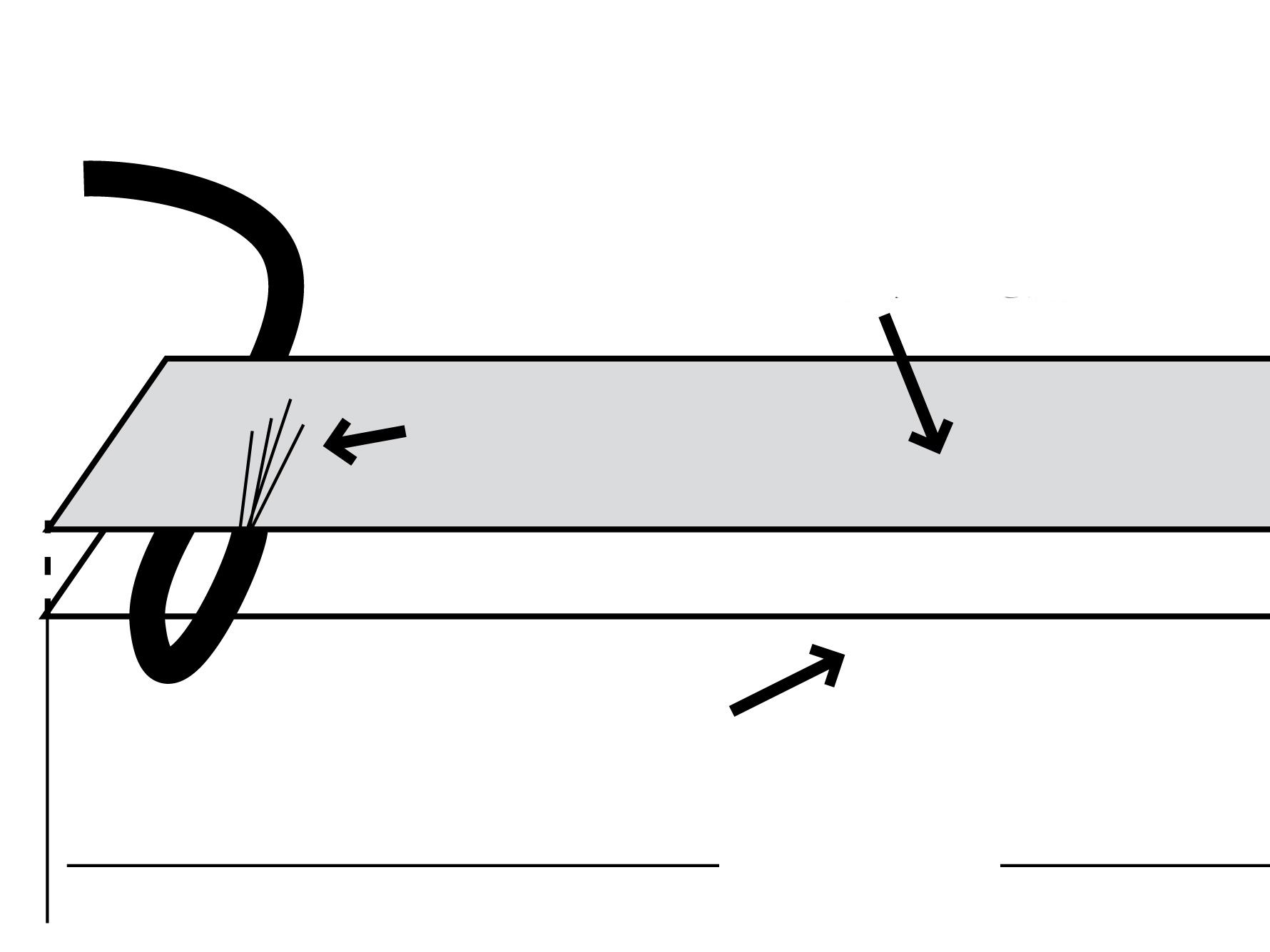
Cut some 3⁄4″ velcro tape into a 3½” piece of loop (soft) side and a 3⁄4″ square of hook (rough) side.

Peel off the tape backing, and align and stick the hook velcro, back to back, at one end of the loop velcro.

Cut a 10″ length of 18-gauge wire and strip 1⁄2″ off one end. Lay the stripped end of the wire perpendicularly across the end of the loop velcro’s sticky side so that its stripped portion hangs off the edge.

Lay a 1″×3″ strip of copper or brass foil over the sticky portion of the loop velcro and wire. Press together firmly and evenly and trim off the excess foil.

Fold the stripped portion of the wire back over the foil and solder it in place. Try to create a smooth, flat surface with the solder that won’t dig into your finger.

Repeat all previous steps for the second sensor.

Strip 1⁄4″ of the sensor wire ends and solder them to a 2-pin header so they may be inserted into the breadboard.

Build the circuit.

The Truth Meter circuit is quite simple. The schematic diagram in Step 4 shows all its electronic components and connections, and this photo shows them assembled using jumper wires on a standard 830-hole solderless breadboard from RadioShack (see https://makezine.com/26/primer for a higher-resolution photo). This section includes the “conceptual steps” for building it, following the GSR’s signal path from sensor to amplified output.

The battery voltage connects to the power rails along each side of the breadboard. The sensor cuffs connect to V+ and V–, with a high-resistance (1MΩ) resistor between V– and one cuff. This resistor acts as a voltage divider, converting the resistance from the sensor into a voltage. Using a high-value resistor this way can introduce noise, but it has the benefit of making the resistance-voltage curve roughly linear over a wide range of skin resistances.

Skin resistance can vary greatly, depending on individual differences, weather, mental state, etc., so our circuit needs to calibrate to a steady baseline. To enable this, a resistor/capacitor (RC) high-pass filter cuts out longer frequencies under ~0.5Hz. This steadies the signal to create a usable baseline while still letting through the shorter GSR signals.

Another RC circuit forms a low-pass filter to remove frequencies above ~5Hz, thus filtering out high-frequency noise such as 60Hz originating from nearby AC power wires.

A series of diodes sets the baseline voltage (from V–) at the op-amp’s input (+) pin to about +1.6V, just below the threshold required to light the red LED. Depending on the diodes’ current/voltage characteristics, this usually requires 3 diodes. Put them in the circuit and use a multimeter to test the voltage drop between op-amp (+) and V–. Add a diode to raise the drop or remove one to decrease it.

For final amplification, so that the output voltage will cross the LED’s threshold with signal spikes, a 100kΩ resistor sets the op-amp’s amplification very high. If the circuit is too sensitive to GSR and the LED flashes too often, swap the resistor between the amp’s (–) input and output for a 10kΩ–20kΩ, or use a potentiometer if you want more control.

Test your truth meter.

Insert your battery leads into the side rails of the breadboard (check orientation, red = V+), slip on the sensor cuffs, and behold your very own Truth Meter. See what happens when someone asks you questions or when you laugh or get surprised. Note the response has a 1- to 2-second delay. Everyone responds differently. See if you can turn the LED on with your mind. Try it on your friends, acquaintances, or adversaries. It’s a great way to get to know someone!

Conclusion

This project first appeared in MAKE Volume 26.