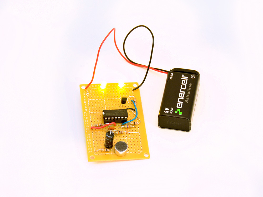
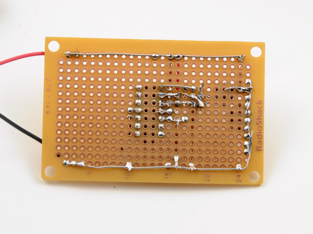
When you are following a schematic, it’s useful to print it out and mark off each connection as you make it. Quite often your circuit board layout will not resemble the diagram, and so, doing this lets you know how much you have completed.
In the second photo here, you can see most of the input stage components added. These are: Microphone, 3x 10kΩ resistors (Brown, Black, Orange, Gold), 2.2kΩ resistor (Red, Red, Red, Gold), 470kΩ resistor (Yellow, Violet, Yellow, Gold), 1µF capacitor and 01.µF capacitor.
Plug the LM324 chip into the socket. Note the chip’s orientation. With the notch pointing up, Pin 1 is top left corner, and the pins are numbered counter-clockwise.
Power it up by inserting the batteries. If nothing starts smoking, that’s a good sign!
To check the output from the first amplifier, I hooked up an oscilloscope to the right hand leg of the 0.1µF capacitor. This showed a sound wave when I spoke – so far, so good!


