finished1

One day a co-worker of mine asked me if I knew of a way to control an irrigation system from a smartphone or computer. We did some research and quickly found that it was very expensive to purchase a system with this capability, so we wondered if we could build it. This happened to be right around the time the ESP8266 first came out, and some quick searching revealed DC water valves that could be used to control water flow to the irrigation system.

When the ESP8266 Wi-Fi module first hit the street, it was very cheap, but the initial attempts to use it included all AT-commands from another microcontroller, so it was a bit clunky. I’d used it like that a couple of times, but never really felt that I could make something reliable enough to use for a project. At this point, we had obtained a DC water valve and done some testing with the ESP8266, then we shelved the project for some months. In those months, some people had ported ESP8266 support to the Arduino IDE, and a new version added the board manager which made programming the Wi-Fi chips easier.

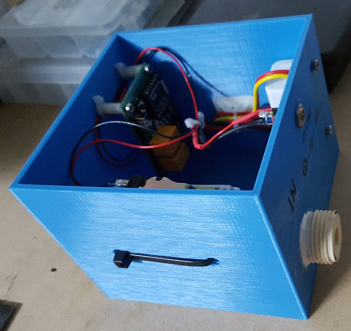
We dusted off the parts we’d ordered and set out with a simple goal: Build a water valve that could be turned on and off remotely. The pictures below are our first working prototype, which used a 3D printed box to hold everything together, and a 12V DC “wall-wort” that I had at my house.

What will the next generation of Make: look like? We’re inviting you to shape the future by investing in Make:. By becoming an investor, you help decide what’s next. The future of Make: is in your hands. Learn More.

Project Steps

STEP 1

Once you have all the parts you need, the first thing to do is assemble the parts on a prototyping board and wire them together, as shown in the wiring diagram. I used the esp-03 module, which can be a pain to use with a standard prototyping board, as the pins on the module are not the same spacing as a prototyping board. I would recommend using an ESP8266 module that is already mounted to a breakout board. Various vendors sell them, and they work very well! Going that route will also eliminate the need to add the programming header typically, as the breakout should include that. A PDF version of this schematic is freely available.

schem

NOTE: The three diodes shown in the schematic are very important and must be installed! If you are curious as to their purpose, research inductor flyback diode.

STEP 2

Once the wiring is completed, we can flash the ESP8266 module with our code, and test its functionality before putting it into the project box.

For this, I used the Arduino IDE and a very slightly modified version of the MQTT Digital Out example from Adafruit. This code utilizes the Adafruit IO system, which is a free to use platform for internet of things messaging. Setting up your dashboard and feeds on the Adafruit IO platform is covered in depth on the Adafruit Learning system, and is a bit out of the scope of this specific project. If you follow along with Adafruit’s MQTT Digital Out example for the ESP8266, you will be walked through setting up the exact dashboard and feed you will need for this project. The only thing you will need to modify from the example code provided by the Adafruit learning system is the GPIO pin used. If you are wired up per the schematic, you will need to change the example GPIO to 14, and add another for GPIO 12. Then add your Wi-Fi SSID and password, as well as your AIO key, and you should be ready to perform a function test.


Void loop() {
Adafruit_MOTT_Subscribe *subscription;
//ping adafruit io a few times to make sure we remain connected
if(! Mqtt.ping(3)) {
// reconnect to adafruit io
if(! Mqtt.connected())
connect();
}
// this is our ‘wait for incoming subscription packets’ busy subloop
while (subscription = mqtt.readSubscription(1000)) {
// we only care about the lamp events
if (subscription == &lamp) {
// convert mqtt ascii payload to int
char *value = (char *)lamp.lastread;
Serial.print(F(“Received: “));
Serial.println(value);
int current = atoi(value);
// write the current state to the power switch tail
digitalWrite(LAMP, current == 1 ? HIGH : LOW);
}
}
}

STEP 3

At this point, you should have a functioning system. The only thing left to do is to mount the assembly in a project enclosure. I used a 3D printed box.

imagejpeg_1

imagejpeg_2

imagejpeg_3