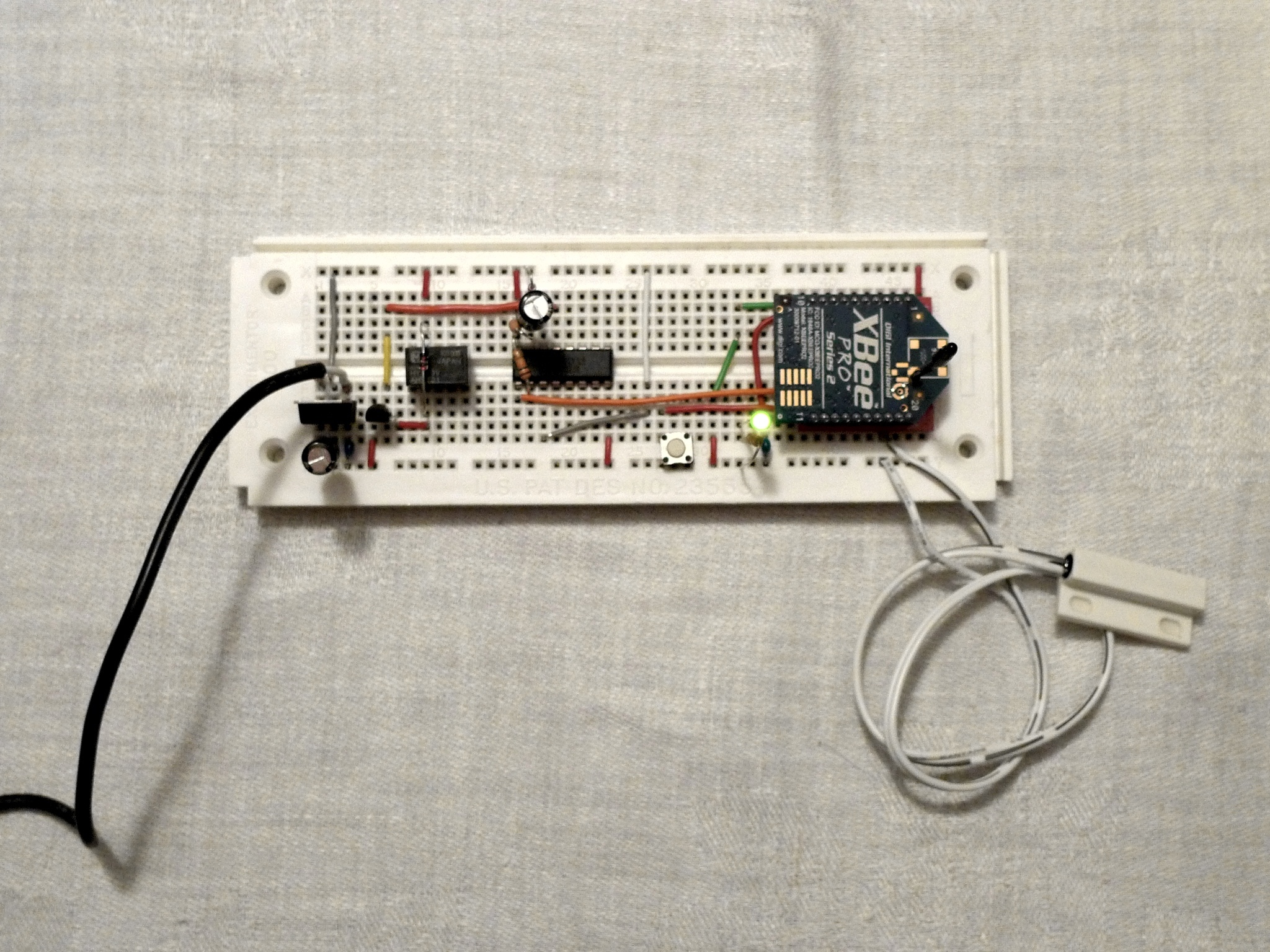
We’re going to lead you through step-by-step instructions to build a prototype XBee Pulse I/O board on a breadboard. This board can be used to automate many things around a home and control them remotely. This design is featured in Make Vol. 30 and is used to connect a garage door opener to a mobile phone.

What will the next generation of Make: look like? We’re inviting you to shape the future by investing in Make:. By becoming an investor, you help decide what’s next. The future of Make: is in your hands. Learn More.

Project Steps

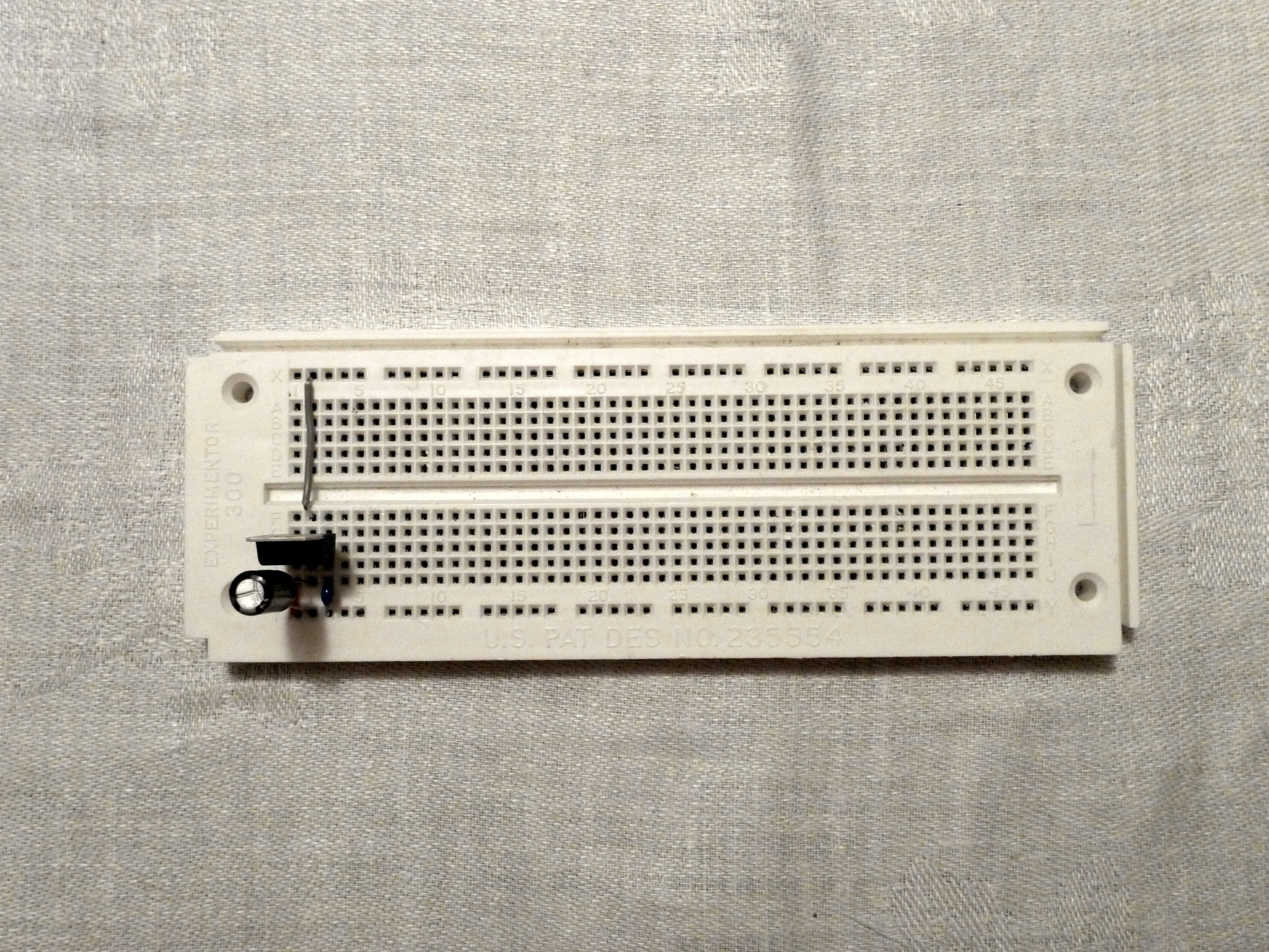
Assembly begins with the power circuit.

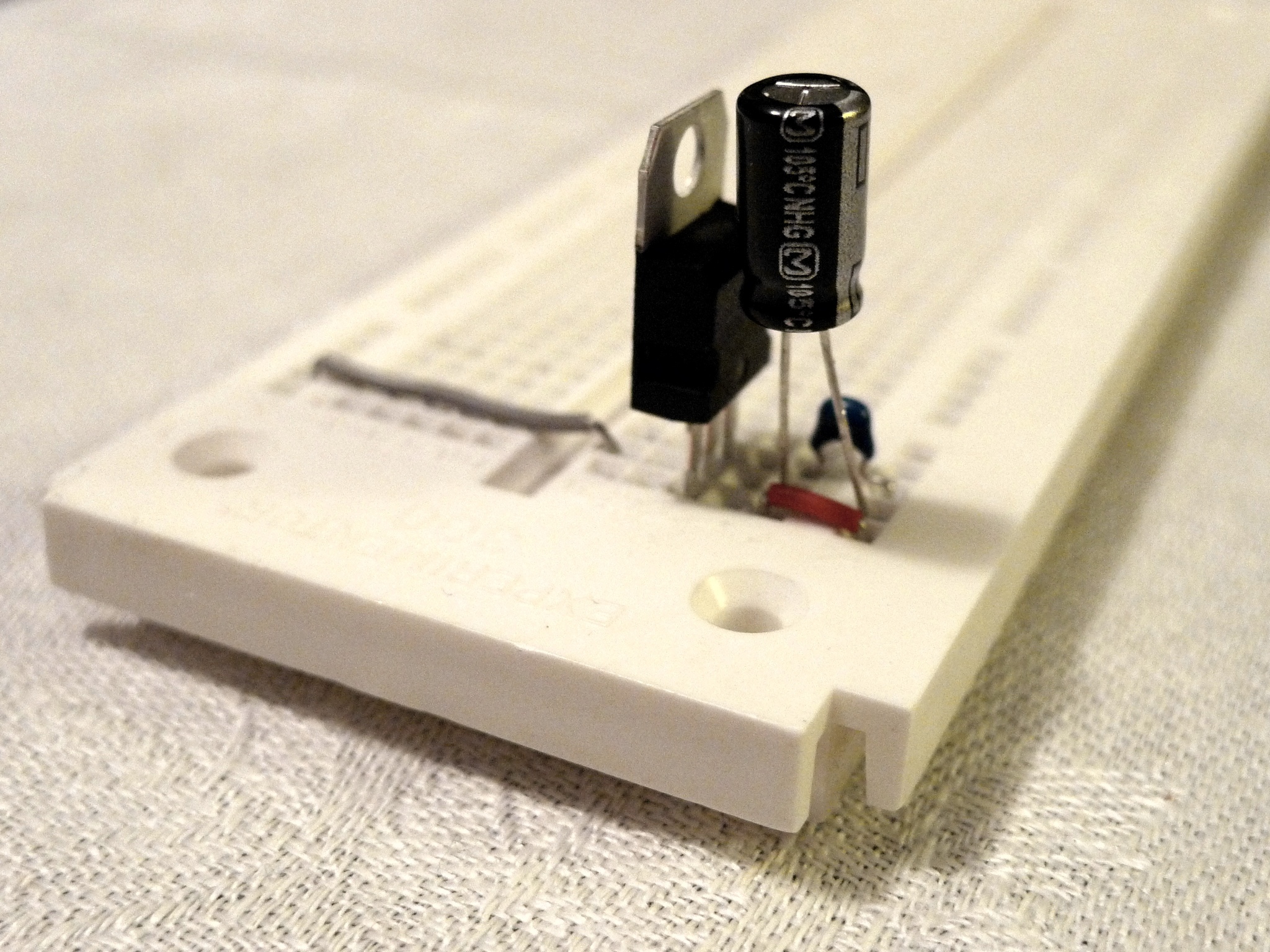
Place the 0.1uF capacitor C8 between the input pin (pin 3) of the 3.3v power regulator VR1 (datasheet) and ground. If you look closely the capacitor has a little “104” written on it.

Place the 10uF capacitor C9 between the output pin (pin 2) of the regulator and ground. Take care to orient the negative pin of the capacitor to ground.

Connect the ground pin (pin 1) of the voltage regulator to ground.

Tie the output pin (pin 3) of the power regulator to one of the breadboard’s power rails so you’ll have easy access to clean 3.3v power when you put in the other components.

Assembly continues by creating the circuit for the XBee. Set aside your XBee module for now; we’ll use it later.

You may insert the XBee breakout board now–note that if you ordered your board from SparkFun you’ll have to solder the headers on. You may find as you work you’ll add and remove the breakout board to give yourself some space, don’t sweat it!

Connect capacitor C4 (10pF) to ground. If you look closely, it will have a little “100” written on it. Connect the other side of C4 to the XBee breakout board’s pin 1.

Continue by also connecting pin 1 of the XBee breakout board to your clean 3.3v power rail.

Connect pin 10 of the XBee breakout board to ground.

Continue by attaching the LED to pin 15 of the XBee, the other pin of the LED to the 180Ω resistor R5 (brown, grey, brown, gold) and the remaining pin of the resistor to ground.

Take care to orient the LED correctly! The long leg of the LED is the anode (positive) and should be connected to the XBee’s pin 15.

This LED will act as our association light and let us know that we’re connected to our wireless network.

Next, connect up the momentary pushbutton switch S1 by connecting it to pin 20 of the XBee.

Connect the other side of the switch to ground.

This switch is our network commissioning button and will let us easily associate and test our XBee’s connection to our network.

Take one wire from the reed switch and attach it to the XBee’s pin 17. Attach the other end of the reed switch to ground.

It’s OK if the wires to your reed switch are short for now—we’ll be testing the sensor before we install it on the garage door.

Next, take a wire long enough to reach midway down the breadboard and connect it to the XBee’s pin 19. Keep it handy; we’re going to use it in a moment.

If you were giving yourself some space by leaving the XBee adapter board off the breadboard, you can place it and leave it now. We’re all done adding wires to that area!

Now we’re going to connect the timer circuit to the XBee. We are going to insert the 74HC123 timer chip IC1 (datasheet). Remember that wire from XBee’s pin 19? Connect pin 1 of IC1 with the wire that is connected to pin 19 of the XBee, inserting the timer chip into the breadboard. Remember, pin 1 is on the same side of the IC as the notch.

Connect pin 16 to the 3.3v power rail and connect pin 8 to ground.

Connect pin 2 to pin 16 using the 10kΩ (brown, black, orange, gold) resistor R1.

Connect pin 3 to 3.3v.

Connect the negative side of 22µF capacitor C1 to pin 14 and the positive side of C1 to pin 15. Connect a 10kΩ (brown, black, orange, gold) resistor R1 between pin 15 and pin 16.

Connect the diode D1 from pin 15 of IC1 to 3.3v, taking care to make certain the striped side connects to 3.3v.

Note the location of pin 13; we’re going to use it in the next step. You’re almost done!

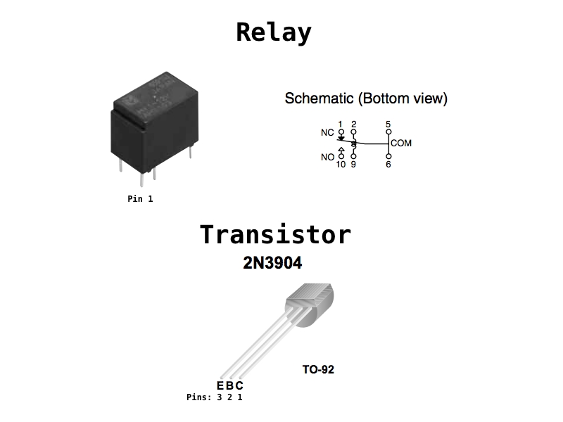
Place the relay (datasheet) on the board. You may have to gently bend the legs of the relay apart to insert it into your board.

Connect pin 9 to 3.3v. Connect diode D2 from pin 2 to pin 9 of your relay, ensuring that the striped side of the diode connects to pin 9.

Locate the NPN transistor T1 (datasheet). Connect pin 1 (the collector) to the relay’s pin 2. Connect pin 3 (the emitter) of T1 to ground. Connect the center pin (the base, pin 2) to pin 13 of the 74HC123 timer chip.

There will be three remaining connections on the relay: the Common terminals (pins 5 and 6), the Normally Closed terminal (pin 1) and the Normally Open terminal (pin 10). Connect a length of wire to one of the Common terminals and another one to the Normally Open terminal. These can be used to connect to your garage door opener for testing.

Finally, connect a 5v-9v power source by connecting the negative wire from the source to the ground of your breadboard and the positive wire of your source to pin 3 of the power regulator VR1.

Here we’re showing two stripped wires connected directly to the breadboard. You could also buy a little adapter board such as product #10288 from SparkFun to adapt your power supply without need to cut, strip and tin anything.

Insert the XBee module into the XBee breakout board.

Follow the remaining steps from the article “Press any Button in Your Home from a Mobile Phone” in an upcoming volume of Make Magazine!

Attached to this step is a schematic if you want to see a diagram of what you’ve built.