Fredrik Jansson is a physicist from Finland, currently living in Amsterdam, where he simulates sea animals. He enjoys cheese, Belgian beer, and tinkering with electronics. Occasionally he blogs about projects together with his wife.
This project is adapted from our forthcoming book Make: Radio, available for pre-order now.
People don’t carry change in their pockets anymore. Or do they?
With the Change Sensor, you can find out. This ultra-simple circuit will also search for hidden treasure — or your house keys, if you drop them in some tall grass. In fact, any metallic object that conducts electricity may reveal itself to you, for this is a basic metal detector circuit. The schematic is shown in Figure A, and the breadboard layout is in Figure B. The symbols labeled X1s, X2, and X3 inside the 4070B chip are XOR logic gates, three of which are active.
Figure A. Schematic of the Change Sensor. Figure B. Breadboard layout. See schematic for component values.
Project Steps
Components
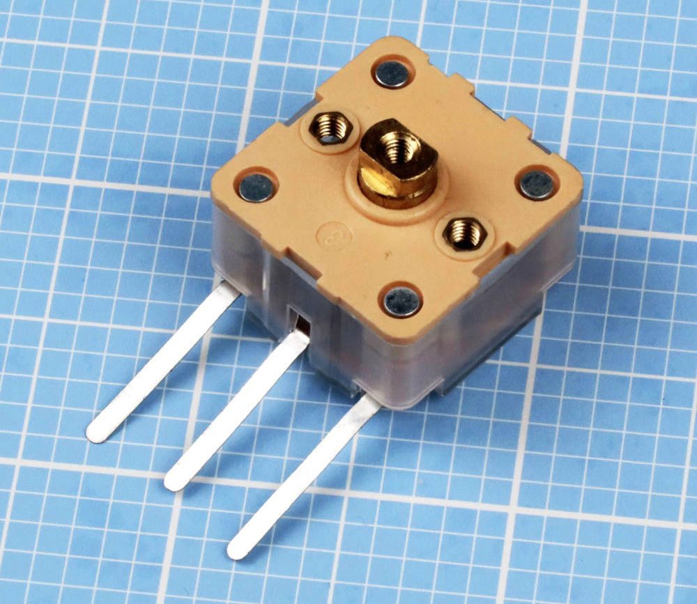
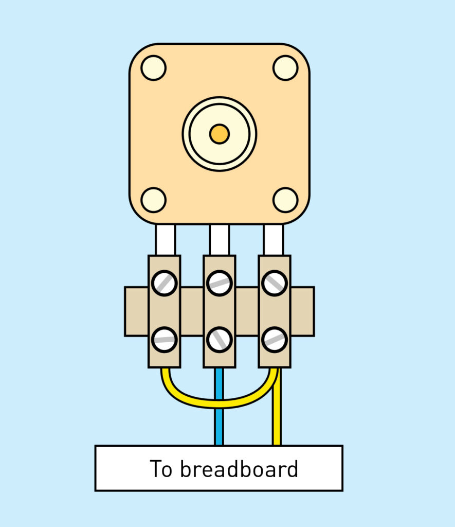
Figure C. The variable capacitor recommended for this project. Photo by Charles PlattFigure D. Connecting the variable capacitor through a terminal block.
The parts on our shopping list are low in price and easily obtained. If you search online for a “200pF variable capacitor,” one of the first hits is likely to be the component we suggest, part number 223P (Figure C). It actually contains two variable capacitors on the same shaft, with maximum values of 140pF and 60pF (picofarads). You need to connect them in parallel, for a total of 200pF. You can use alligator jumper wires for this, but a terminal block with screws spaced at 5/16″ (8mm) is better (Figure D). The center terminal should go to negative ground on your breadboard.
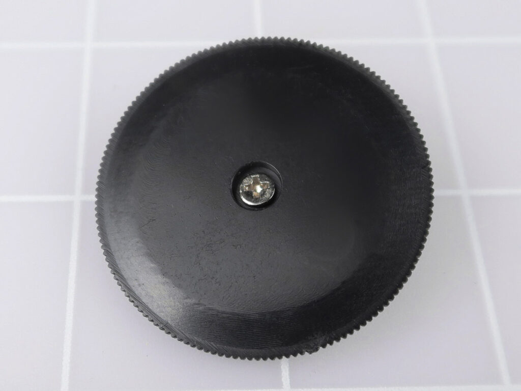
Figure E. A plastic wheel should be added to your variable capacitor. Photo by Charles Platt
Wherever you buy your variable capacitor, also buy a plastic tuning wheel (Figure E) which screws onto the shaft, to prevent the touch of fingers from affecting the capacitance.
Figure F. An inductor is easily mistaken for a resistor. Photo by Charles Platt
The inductor in our list (Figure F) can be found at any large electronics supplier. It looks like a resistor, but inside it is a coil of very fine wire. Its value is expressed in microhenries, written as μH.
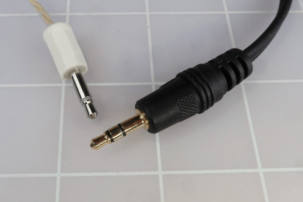
Figure G. You can use any earphone with a 3.5mm mono plug (left) or stereo plug (right). Photo by Charles Platt
The circuit will signal you via an earphone. If you can find a high-impedance type, often sold “for crystal sets,” that’s ideal; but any earphone(s) terminating in a 3.5mm jack plug will work. See Figure G.
Figure H. How to wire different types of audio adapter.
To connect the plug to your breadboard, search online for a “3.5mm jack terminal block connector.” Its screws may be identified as T, S, and R (for the tip, sleeve, and ring of a stereo plug), or L, R (left and right stereo channels), and a ground symbol. Figure H shows how to connect either type of adapter when using stereo or mono headphones. The blue wire goes to negative ground in each case, while the yellow wire carries the signal.
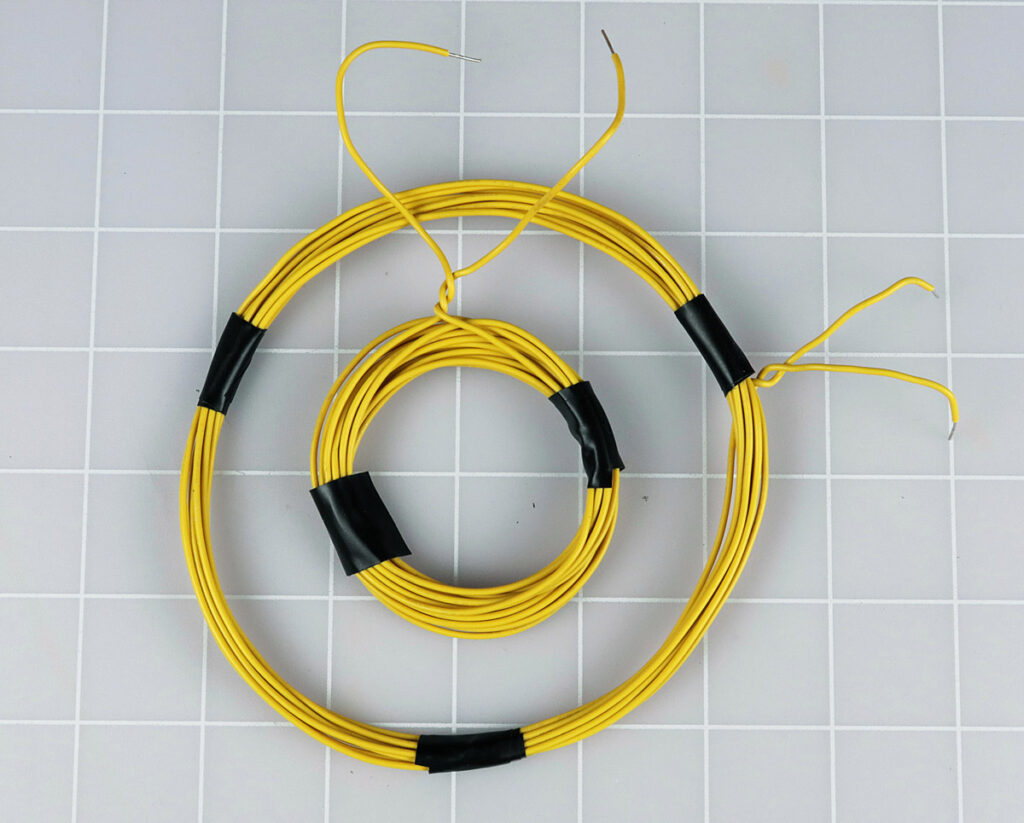
Figure I. The 2″ coil contains 17 turns of wire. The 4¼” coil contains 10 turns. Photo by Charles Platt
The yellow sensor coil shown in Figure A can be adjusted to suit your interests. A smaller-diameter coil will be more sensitive to small objects such as coins. A larger coil will respond to large objects. In Figure I, the large coil is 4¼” diameter, created by wrapping 10 turns of 22-gauge hookup wire around a 2-liter bottle of soda. The smaller coil contains 17 turns, 2″ in diameter. Try them one at a time.
Seeking a Signal
After you connect your coil and attach a 9V battery, turn the variable capacitor until you hear a sudden whistling sound. Now turn the capacitor very slowly until the sound goes lower in pitch and finally disappears. Keep turning, and it should reappear and rise in pitch. Back up and set the capacitor at the silent spot between the falling and rising frequencies.
Now move a metal object over or into the coil, and if the object is similar in size with the coil, the circuit will whistle in response.
What if you hear nothing at all? Add a turn of wire to your coil, or subtract a turn.
The Concepts
If you’re wondering how this simple circuit magically detects metal, the answer involves capacitance and inductance.
Capacitance measures the ability of an object to store extra electrons. The capacitors in a circuit can do this, and your body can do it, too. If you ever feel a little shock when touching a metal object such as a door handle, your body just discharged some electrons which it had accumulated relative to the environment.
In an electronic circuit, when you apply voltage to a capacitor that has no charge, it sucks up some current as electrons accumulate on one of its plates. Gradually the current diminishes until the capacitor is fully charged.
Inductance is the ability of electric current in a wire to induce a magnetic field. This effect is multiplied when the wire is coiled. When you apply voltage to a coil, initially the current seems to encounter resistance, because energy is being taken to create the magnetic effect. After the field is stable, when you disconnect your power supply, there is a sudden reversed surge of current that is created by the field collapsing.
Figure J. The concept of an oscillator using a coil and a capacitor in parallel.
The two components seem to have opposite personalities. The capacitor sinks a surge of current and then gradually blocks it; the inductor blocks a surge of current and then gradually lets it flow. What would happen if you put a capacitor and an inductor in parallel, as in Figure J?
If you use the switch to supply a brief pulse of current, initially the coil blocks the flow while the capacitor acquires a charge. Then if you open the switch, the capacitor discharges through the coil. When the flow ceases, the magnetic field collapses, sending current back to the capacitor and recharging it with opposite polarity. At the end of that cycle, the capacitor discharges again, and the sequence repeats. This is sometimes known as a tank circuit because current is sloshing around like water in a tank. More accurately, it is an oscillator.
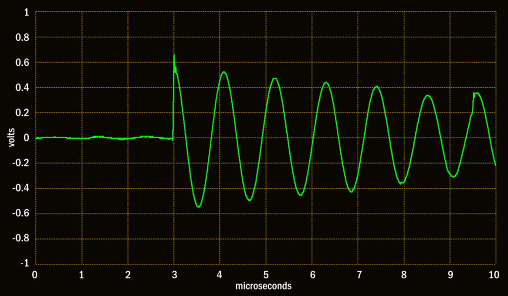
Figure K. Decaying oscillations in a tank circuit after a brief pulse is applied.
Figure K shows the voltage in the circuit in Figure J after the power is pulsed very briefly. The circuit has a small amount of resistance, so the current gradually loses energy in the form of heat, and the oscillations die away.
But in our circuit, logic gates X1 and X2 feed back just enough power into O1 and O2, through resistors R1 and R2, to keep the oscillations going. The frequency is then determined by capacitors C1 through C5, the value of the inductor, and the diameter and number of turns of the sensing coil.
Oscillators are fundamental in radio, when you want to receive a station or change the frequency of a transmission. We have been writing a book titled Make: Radio which will be out in 2024, in which we go into the topic in much more detail.
Mixing Oscillators
When you apply voltage to a coil, it can induce tiny amounts of current in any nearby object that conducts electricity, and this changes the frequency of the circuit containing the coil. Because metal objects are conductive, the coil will react if it senses some metal nearby.
The only problem is that if we choose a variable capacitor and inductor that are conveniently and affordably small in size, the circuit will oscillate at a frequency that is much too high to hear. We can get around this limitation by enabling you to hear the difference between O1 and O2.
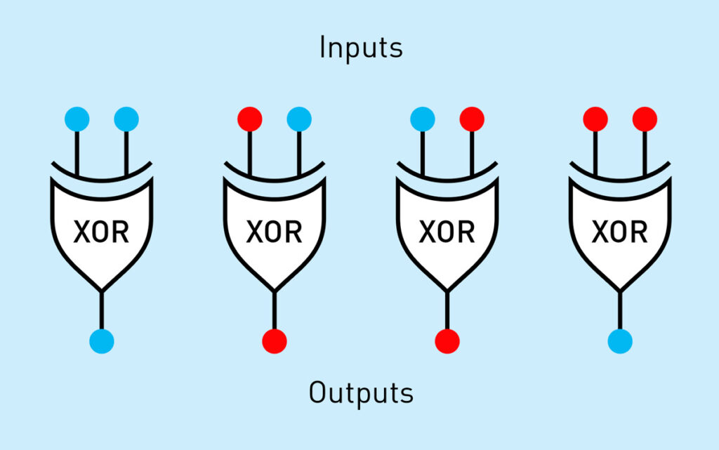
Figure L. Inputs and outputs using an XOR logic gate.
Remember how an XOR gate works. Its output is low when both inputs are the same, and high when the inputs are not the same, as shown in Figure L, where blue dots indicate 0 volts and red dots indicate supply voltage.
In our circuit, you begin by setting O1 and O2 to the same frequency, around 2MHz; this occurs when you hear silence in your headphones. Now any disturbance will cause O1 and O2 to go out of phase, thousands of times per second — at an audio frequency.
X3 mixes the signals from O1 and O2 before passing its output through R3 (which protects the logic chip from delivering excessive current). Capacitor C6, with R3, functions as a low-pass filter: it grounds high frequencies and only allows audio frequencies to reach the headphone jack.
Figure M. How an XOR gate combines oscillations that go in and out of sync.
When O1 and O2 are almost synchronized, the output from X3 is “off” most of the time. But when O1 and O2 are out of sync, the output from X3 is mostly “on,” as shown in Figure M. The small fluctuations are eliminated by the low-pass filter, but the transition between “mostly off” and “mostly on” is audible in the earphone. You can add an audio amplifier such as an LM386 if you want the sound to emerge from a small speaker.
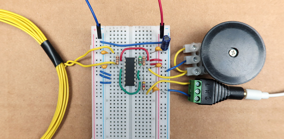
Figure N. The assembled circuit. Photo by Charles Platt
Maybe you’ve seen security personnel at airports waving a wand around, searching for metal objects under people’s clothes. Our Change Sensor is not as sensitive as that, because it only uses a handful of components (Figure N). But the principle is much the same.
Conclusion
This article is excerpted from the forthcoming book Make: Radio and also appeared in Make: Volume 87.
Fredrik Jansson is a physicist from Finland, currently living in Amsterdam, where he simulates sea animals. He enjoys cheese, Belgian beer, and tinkering with electronics. Occasionally he blogs about projects together with his wife.
Our websites use cookies to improve your browsing experience. Some of these are essential for the basic functionalities of our websites. In addition, we use third-party cookies to help us analyze and understand usage. These will be stored in your browser only with your consent and you have the option to opt-out. Your choice here will be recorded for all Make.co Websites.
Allow Non-Necessary Cookies
Ready to dive into the realm of hands-on innovation? This collection serves as your passport to an exhilarating journey of cutting-edge tinkering and technological marvels, encompassing 15 indispensable books tailored for budding creators.