YouTube player

Computers add binary numbers constantly, but we never see how. This elegant machine does the math using glass marbles.

I started building marble track machines years ago using Lego. I experimented with all sorts of crazy ways for the marbles to descend. One was a rocker that shunted a stream of dropping marbles one-by-one to alternating sides. If you cascade three of these toggles down to the left, every marble flips the rightmost toggle, every second marble flips the middle toggle, and every fourth flips the leftmost. Interpret each toggle’s state as left = 0 and right = 1, and you have a binary counter. Add more toggles, and it can count more.

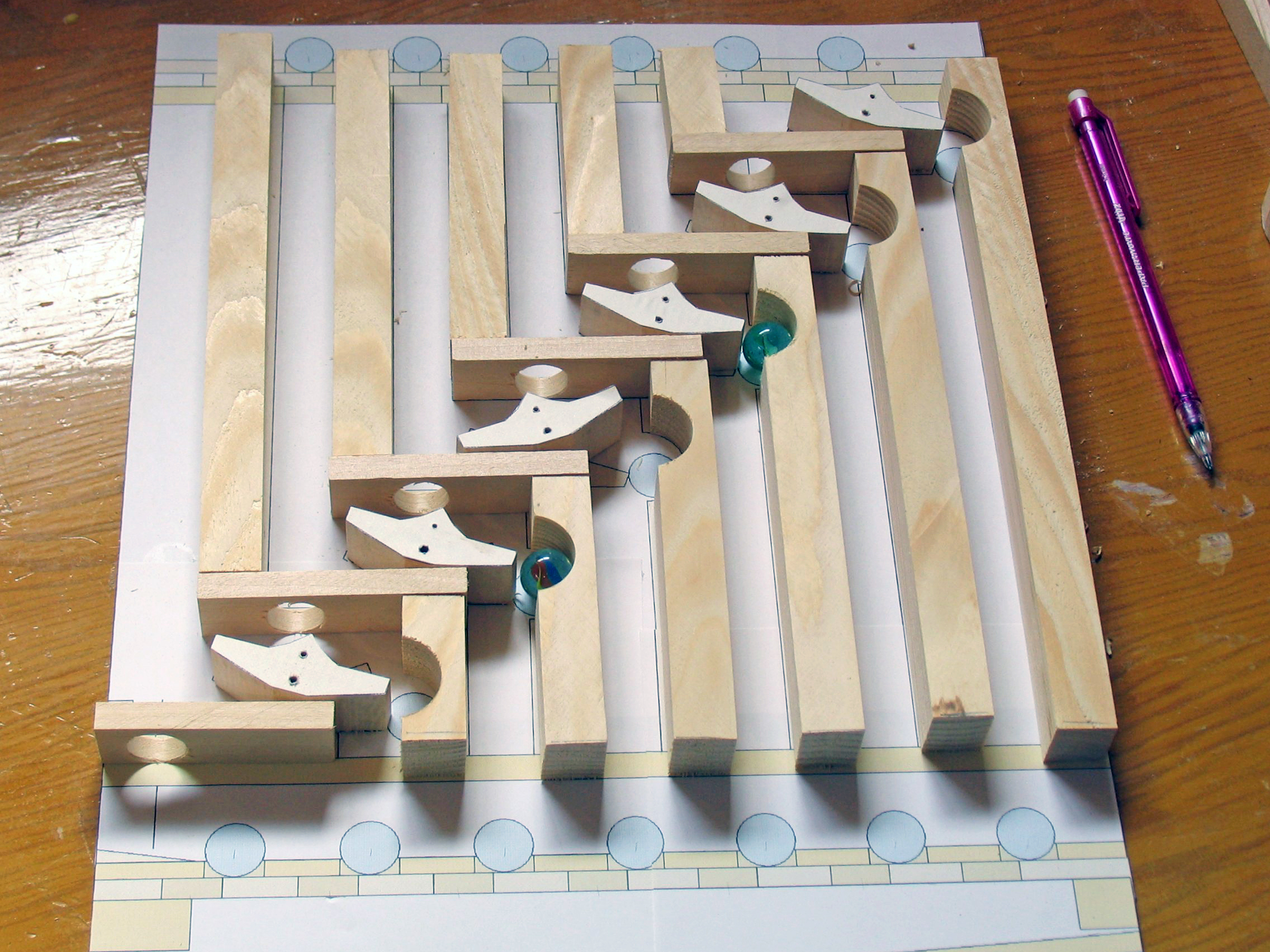
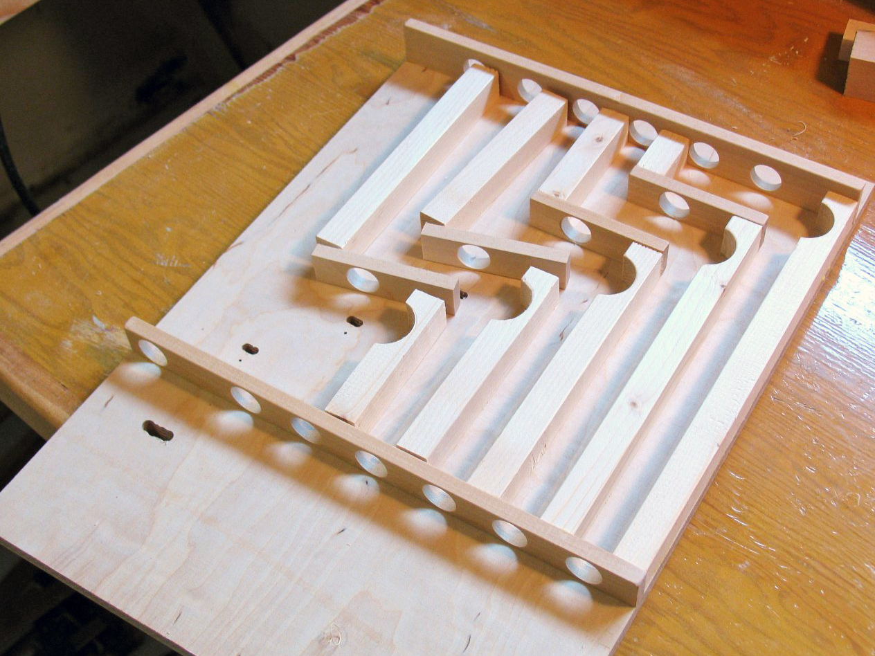
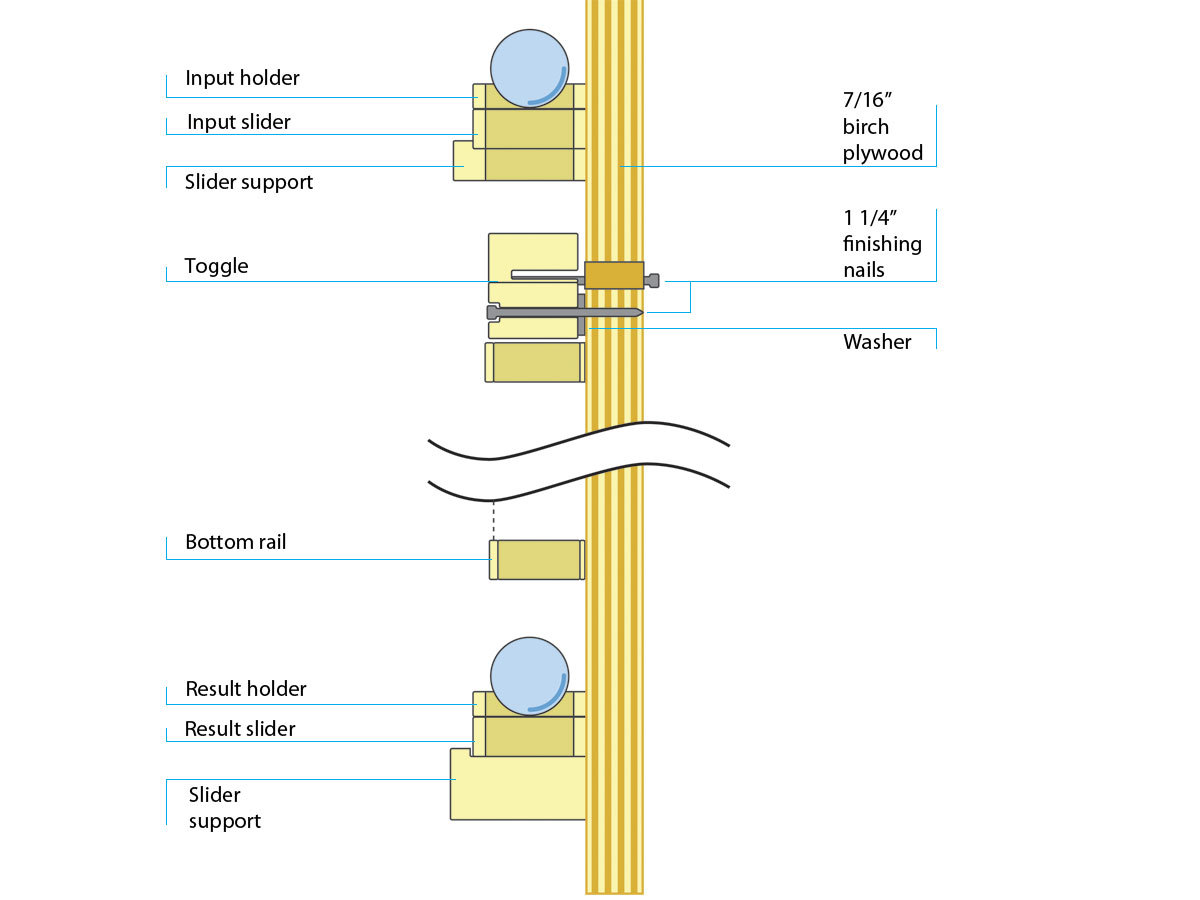
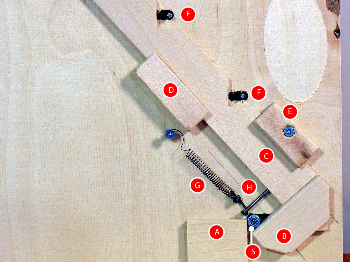
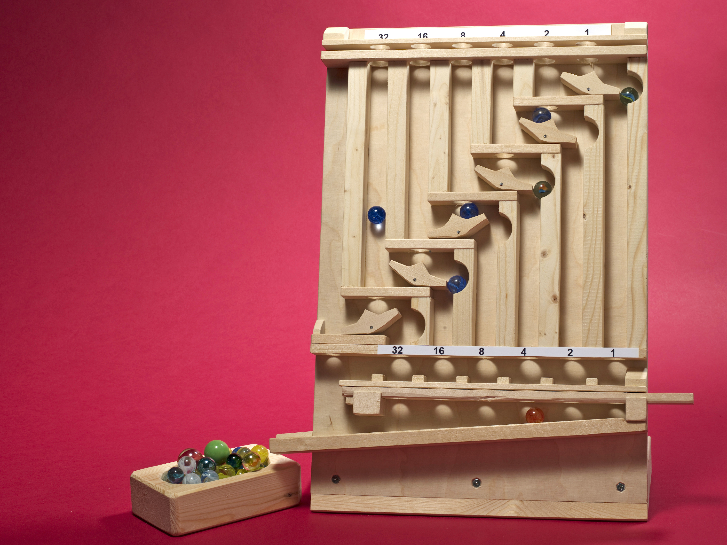
I realized I could turn the counter into an adder by dropping marbles onto toggles other than the rightmost. I added a marble hold-and-release shelf up top to act as an input buffer, another underneath as an output buffer, and a clear-register mechanism to reset all toggles. I moved from Lego to wood, and refined the design a few times. Here’s the latest edition.

Project Steps

Mark the layout on the blackboard.

You can use my project plans, or you can design your own. Note that I use metric measurements in general, but standard sizes for the drill bits and some materials.

Download the project plans from https://makezine.com/20/marble_adder and print them at full size, not scaled. If you can print oversize, use the full template plan.png. Otherwise, print out the tiled version, plan_p1 through plan_p4, and align and glue the 4 pieces together. Also print at full size the templates toggles_template.png, for Step 2, and sliders.png, for Step 3.

Cut the plywood to 400mm×280mm and clamp the template centered on top.

Transfer the key locations from the template onto the plywood. For the positions of the holes, I used an awl to punch through the template and into the wood. For the horizontal and vertical pieces, I transferred the positions of key corners by punching lightly through the paper with a chisel. Be sparing in how many places you mark, and circle the points on the template where you marked the wood, so that after you remove it, you can still figure out what corresponds to what.

Cut the toggles.

Each toggle uses two 1¼” finishing nails: one provides the pivot that it spins around and the other sticks out the back for the reset mechanism. Use a closed-grain hardwood for the toggles and horizontal pieces, so they can withstand all the marble impacts.

Cut out the 6 paper templates from the toggle template you printed in Step 1, and glue them onto 1×4 hardwood. Use a band saw or jigsaw to cut the shapes out.

For the pivot nail holes at the bottom, drill a centered 3/64″ hole all the way through and countersink it with a 3/32″ hole 2mm deep for the nail head to sit flush. For the reset nails, drill a 1/32″ pilot hole from the back, going only 12mm deep.

Sand the template paper off the toggles.

Cut the verticals and horizontals.

Cut the 11 vertical pieces, following the plan. I used spruce 2×6s. All are 19mm thick, front to back, and 18mm wide. Start with the 5 top pieces, which are just simple rails.

For the 6 bottom vertical pieces, which have a cutout next to the toggle, cut 3 pieces just over 36mm wide. Using a 1 1/8″ Forstner bit, drill holes centered 24mm down from the top, then cut the rails down the middle and trim to length. Don’t cut the holes with a spade bit, since that probably won’t cut cleanly. If you don’t have a 1 1/8″ Forstner bit, you can cut the rounds out with a fine band saw blade or a scroll saw.

Follow the template sliders.png that you printed in Step 1 to cut and drill the horizontal pieces: a feeder above each toggle, the input holder, input slider, input slider holder, bottom rail, result holder, result slider, result slider support blocks, and clear ramp. All holes are 11/16″. I added some extra length to the clear ramp, not on the template, so the marbles could dump into a bowl more easily.

As you cut the pieces, check them by laying them down in place on the paper template

Deburr all the marble holes and use a knife or file to make a chamfer on the topside of each. Cutting against the grain will splinter the wood, so each hole requires a separate cut for each quadrant.

Assemble the front.

In the backboard, drill the 1/32″ pilot holes for the toggle pivot nails. Above them, drill the holes for the toggle reset nails — two ¼” holes next to each other — then use a small saw or file to join the 2 holes, making an oblong shape. Drill and cut another oblong aperture for the stop screw at the left end of the result slider.

It’s time to start gluing pieces to the backboard. First, glue down the input slider holder and bottom rail. Let the glue dry.

Working from one side, glue down sets of 2 uprights and 1 horizontal for each bit position.

Glue down the input holder and result slider support blocks (2nd photo). To make sure the sliders have enough room to slide comfortably, cut slider-sized spacers out of thin cardboard and sandwich them in with the sliders as you position the new pieces for gluing. Make sure the sliders remain unglued.

Glue down the clear ramp. (So marbles wouldn’t fall off my extension to the clear ramp, I added a back piece there, which isn’t in the template.)

(Optional) For aesthetics as much as anything, I glued beveled blocks at either end of the input holder and between the bottom rail and result holder. I also added small blocks between each result holder hole. These are not in the template.

Attach the toggles. Nail the pivot nails into the back panels, threaded through the toggles with a small washer underneath. Turn the assembly over and nail the reset nails through the elongated holes into the other side of each toggle so that they protrude about 6mm.

Add the release mechanism and base.

Screw a 1½” #6 wood screw into the bottom slider, through its oblong hole in the backboard of the machine.

Make the diagonal slider. It’s best to size this to your machine’s actual dimensions, rather than from plans. Tilt all the toggles to the 1 position (right in front, left in back). Cut a slat of birch 5mm thick and 23mm wide, and push it up against the nails in back. Use a pencil to mark where the nails touch the slat, then cut vertical notches down and to the right from each, so that they run under the oblong holes.

For the next three bullets, the reference position for the diagonal slider is to the left (facing the back), with all toggles in the 1 position (see photo).

Slide the bottom slider screw to the left in its hole. Referring to the photo, cut and glue block B to the bottom end of the diagonal slider (C), so that it hooks under the screw.

Mark the left edge positions of the diagonal slider and block B. Cut and glue block A so that it rests against block B as a stop.

Hammer a nail (H) into the bottom edge of the diagonal slider, hook it with a small spring or rubber band (G), and anchor the other end of G to the backboard with a ¾” #4 wood screw, so that it pulls the slider up and left, into the 1 position.

Slide the diagonal slider up and to the right, perpendicular to its length. It should engage the slider screw and toggles so that they all flip to the 0 position. Mark its right edge.

Cont'd.

Cut L-shaped blocks D and E to stay the diagonal slider on each side, making sure it will still slide between 0 and 1. Glue D to the backboard and attach E with a ¾” screw, to make the slider removable.

For the base, bevel a piece of 2×6 wood with a 20° angle, then drill and screw the bottom of the backboard to it. I used three 1½” #6 wood screws, spaced out. That’s it; you’ve made it!

For reinforcement (optional) you can run a vertical strut from the base to the top of the backboard, as I did with my prototype (as in the photo).

Design your own.

If you want to use your own template, try prototyping a 1-bit adder first, since it’s tricky getting a toggle shape and configuration that work reliably.

To test the whole machine later, put it together using just hot glue for the non-moving pieces so you can pry them off to reshape or reposition them.

The MSB (most significant bit) marbles on the left have a long drop, so you should confirm that they stay on track and don’t bounce out.

Conclusion

Debugging

Chances are, your machine will need a bit of debugging to get it working perfectly. Filing here and there will smooth the marbles’ journey.

Hopefully, the 20° angle will keep marbles from getting ejected out the front of the machine, but if they do fall out, it may help to carve out the back edges of the holes that the marbles pass through. You can also just re-bevel the base to mount the machine at a 30° angle instead of 20°.

Adding Value

For maximum marble action, add 63 (111111 in binary) to 63.

It’s also fun to use the adder for subtraction and negative numbers by using the two’s complements of numbers. This means interpreting the leftmost bit as the positive or negative sign, and flipping all the other bits to convert from positive to negative. For our 6-bit adder, this gives a number range from –31 (100000) to 31 (011111). Adding –1 to –1 is the same operation as adding 63 to 63 above, and it results in 111110, the 6-bit two’s-complement representation for –2.

In general, it’s fun to subtract 1 from numbers, because nearly the same number results, but with all the original marbles dumped and replaced by new marbles.

I invented my marble adder independently, but people have since emailed me about 2 educational games from the 1960s with which it shares some similarities, named Dr. Nim and Digi-Comp II.

Multiplying Possibilities

I have spent time trying to come up with multiplier designs, but everything I’ve thought of lacks the gee-whiz simplicity of the adder. I’d want to multiply not by adding the number to itself N times, but by shifting the number to be added, and adding it to the other argument in each shifted position. Such a machine would no doubt involve a lot of sequencing and require gears and such, but I haven’t come up with a specific design that has simple appeal.

Suggestions are welcome!

This project first appeared in MAKE Volume 20.