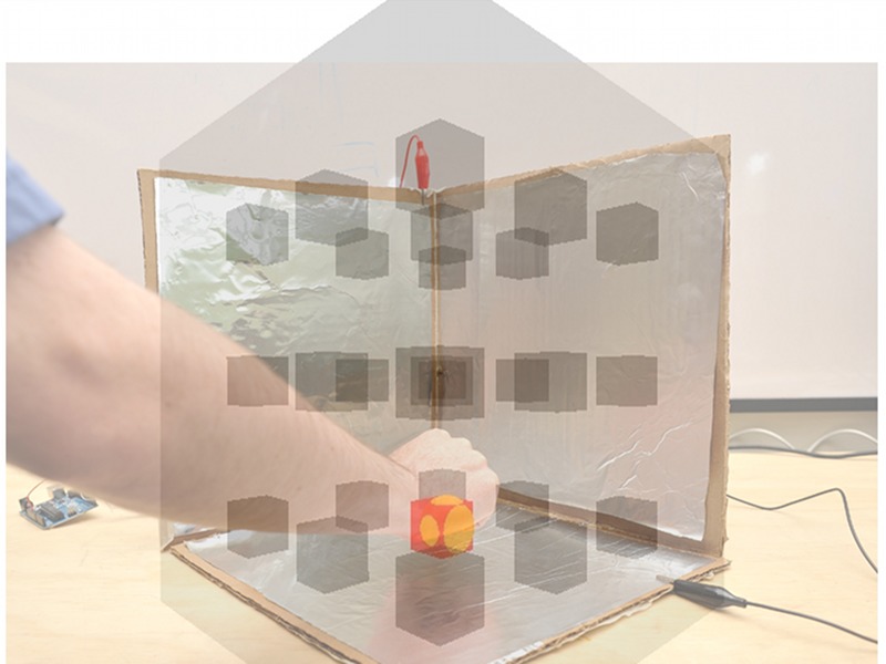
In this project, we’ll take a very simple idea — the length of time it takes a capacitor to charge — and make something rather amazing with it: a 3D interface that can track the position of your hand. The original implementation of this project comes from media artist Kyle McDonald.
Project Steps
Making the sensor cube.
For this project we’ll need some cardboard squares (mine are approximately 12″ square, but anything from about 8-12″ is fine), alligator clips, an Arduino, shielded wire, aluminum foil, spray glue, and some wide tape. (3) 10KΩ and (3) 220KΩ resistors are also required (not shown).
Additionally, we’ll need a soldering iron to connect the resistors to the cable.
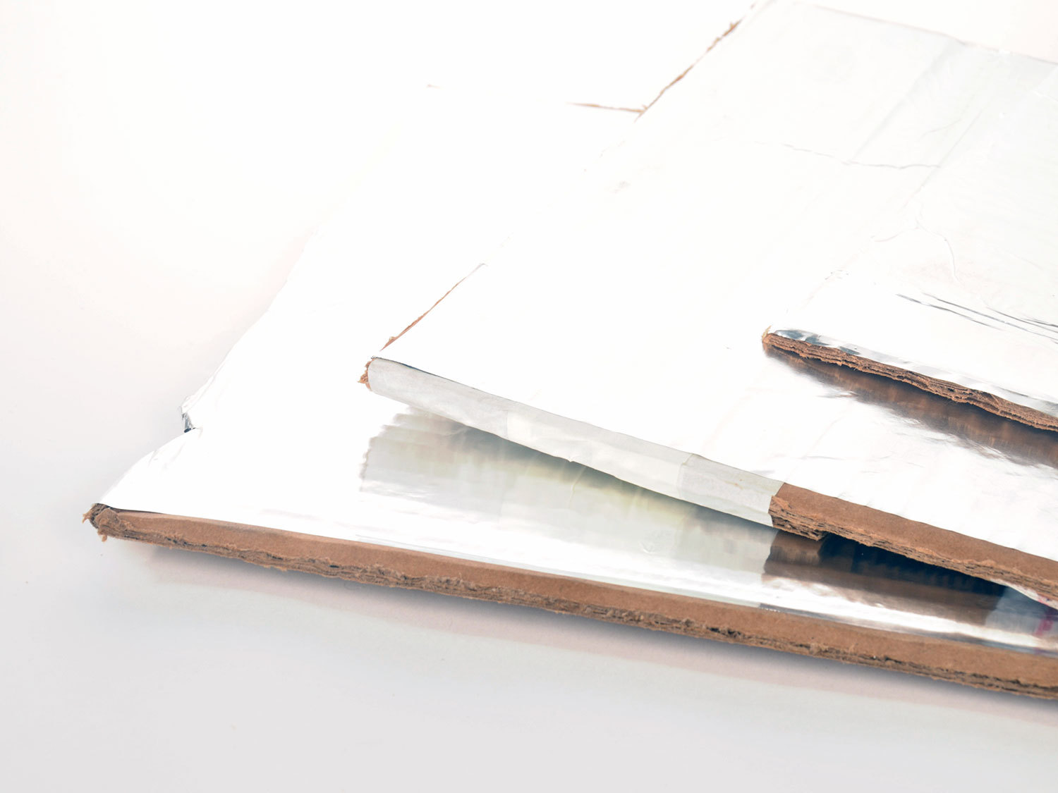
Spray the glue onto the cardboard and smooth the foil onto one side. Work slowly and try to leave a small gap around the edge of the foil. It is important that the foil plates do not touch each other when we tape the three sides together. In a pinch you can use a glue stick.
I cut a small notch in the inside edge of the rightmost plate to make it easier to connect the alligator clips later on (see second photo).
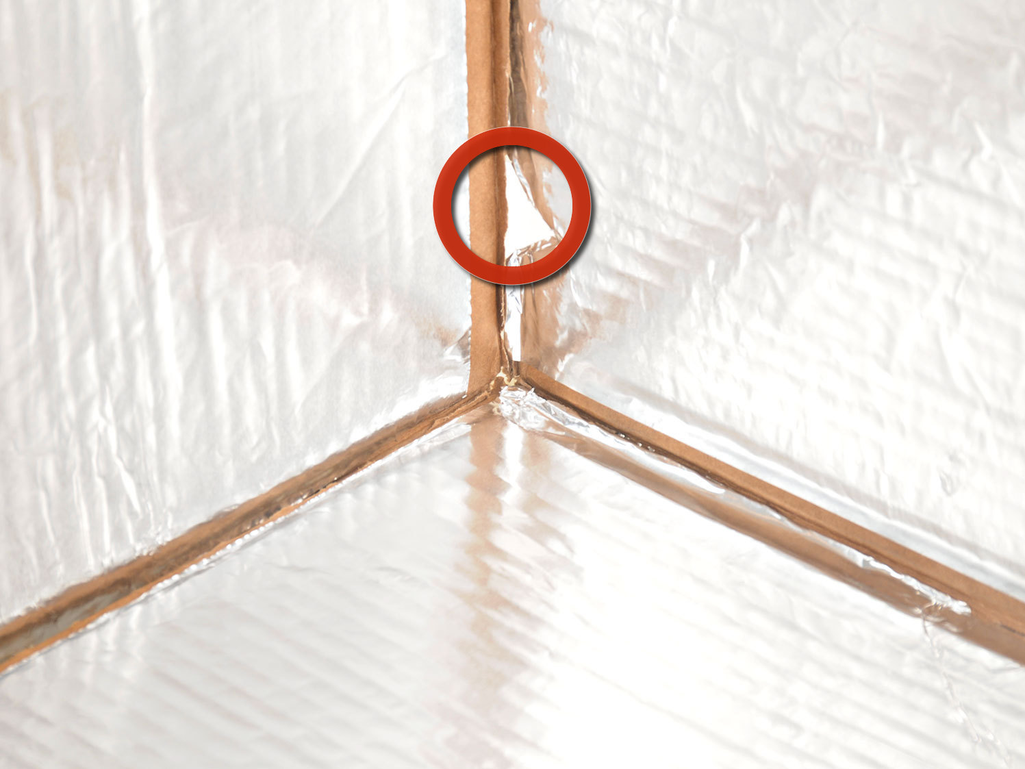
Using tape, assemble the plates to form one half of a cube (see the third photo).
Prepare the wires.
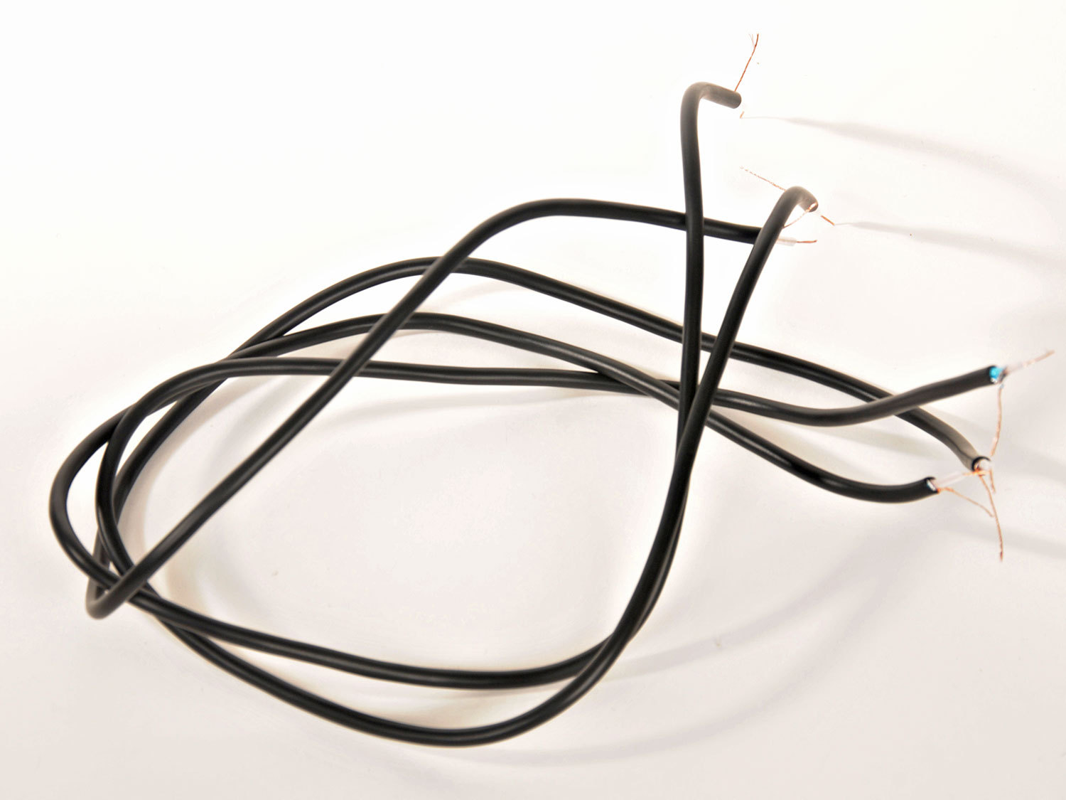
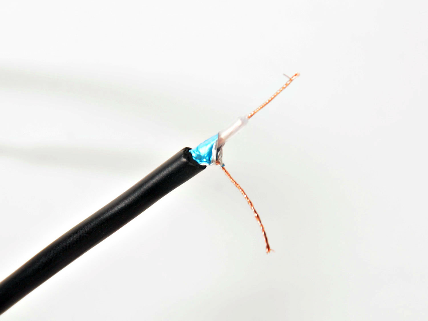
Next we need to prepare the wiring. I bought a 6′ shielded audio cable for this. It is important to use shielded wire so that the cable itself doesn’t act as an antenna and skew the sensor readings.
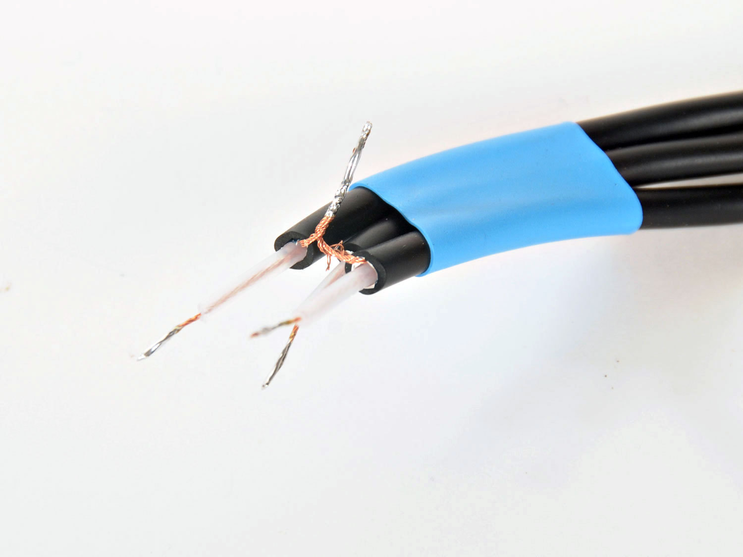
Cut the wire into 3 pieces of equal length (2′ or so) and strip off the outer and inner insulation (second photo).
On one end, trim off the shielding wire and connect just the inner signal wire to an alligator clip (third photo).
Adding the resistors.
On the other non-alligator end of the cables, twist together the 3 shield wires and solder them. The shield will be connected to the 5V pin on the Arduino. This will minimize the antenna effect of the cable on the circuit.
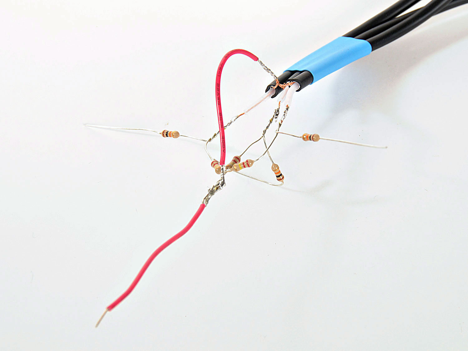
Referring to the schematic, connect the resistors to the three inner wires of the cables as shown and connect this to the ends of the three wires. The 220KΩ resistors all connect between the inner wire of the cable and 5V. The 10KΩ resistors will each be connected between the end of the cable and a pin on the Arduino. The circled area indicates that this wire should be shielded, with the shield connected to +5V.
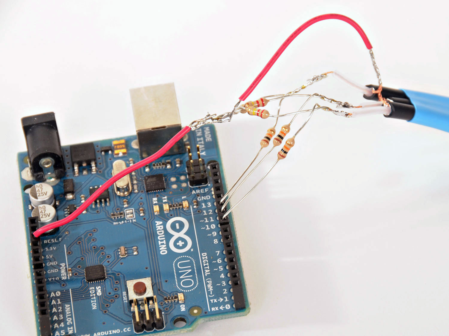
Use a small piece of jumper wire to make the connection between the shield wires and the 5V output pin on the Arduino, as shown in the third photo.
In the picture, I have used some blue heat shrink tubing to hold the three wires together. You could also just tape the wires together.
Connecting the Arduino.
Connect each of the 10KΩ resistors to pins 8,9, and 10 respectively. Connect the red wire to the +5V pin on the Arduino.
Attach each of the alligator clips to a foil plate. The clips should be attached in the following order: pin 8=left plate (x), pin 9=bottom plate (y), pin 10=right plate (z). Make sure that each clip is making good electrical contact with the foil and is only touching one plate.
When troubleshooting, check the connection between the plate and the pin with a multimeter to make sure the alligator clip is making a good electrical contact.
From the Arduino IDE, upload the sketch to the Arduino. Keep the USB cable connected to the Arduino, then install and load the Processing sketch.
It is important that your computer is plugged into the wall for this to work properly. If the circuit isn’t connected to earth ground (at least indirectly though your computer) you may find that your computer itself will affect the circuit.
The next thing to be done is calibrate the software. With the Processing sketch running, hold down the left mouse button. Then move your hand from the far outer diagonal corner (i.e., the invisible corner of the cube closest to you) to the inner corner. Don’t touch the foil, just move your hand through the space defined by the cube. Now release the mouse button. The path your hand traveled gives the software a chance to detect the range of motion your hand will make inside the cube.
Now move your hand around inside of the cube. There should be a sphere on the screen through which you can control and move to touch all 27 cubes inside the computer model. Pressing tab will change the color of the cubes.
This is the simplest form of capacitive sensing available. In the final section, we’ll look at some alternative solutions and options to improve the system.
Possible improvements.
Increasing the resistor values – the 220KΩ resistors form part of the RC network and it’s worth experimenting with different values. Typical values are 200KΩ to 500KΩ. The responsiveness of the system will be affected by these values. You can also tweak the values in the “Normalize” tab of the Processing sketch to calibrate your particular configuration.
A more solid connection with ground. Since the Arduino is connected to the computer, and the computer is connected to the wall socket ground, this is generally good enough to provide a consistent reference to ground. If you have a house ground connection available you might want to connect this to the Arduino ground pin and see if that improves the response.
If you decide to connect anything to the house wiring, be very sure that it really is a ground. A good earth ground would be a water pipe.
The CapSense library is an excellent capactive sensing library for Arduino. The page includes some good information on configuring capacitive sensing circuits.
Terry Fritz (a well regarded Tesla Coil experimenter) put together a neat “vision” system for robotics called ThereminVision. It uses tuned oscillators and heterodyning to implement a theremin circuit. Definitely worth a look.
Conclusion
In this guide, we introduced the concept of capacitive sensing. Nearly all sensing of this kind depends upon how long it takes a capacitor to charge (known as the time constant). Placing an object within the electric field of a capacitor will affect the capacitance value and the corresponding time constant. See the RC time constant entry on Wikipedia for more information.
We hope you appreciate the cleverness of this project as much as we did and how relatively easy it is to get a very 21st century interface (however crude) out of some aluminum foil and a cardboard box! We'd love to hear of your experiences with the build (in the comment section below).