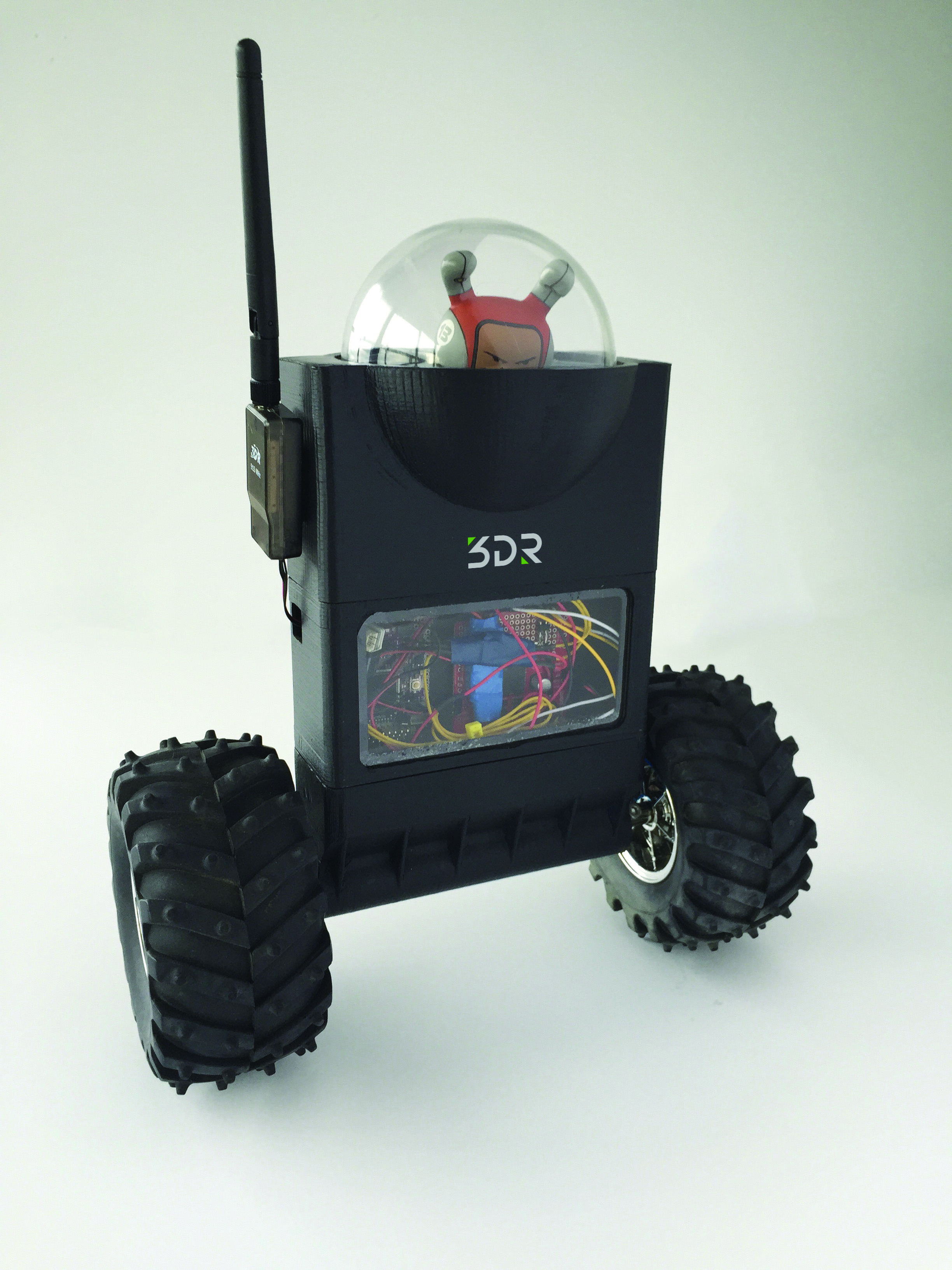

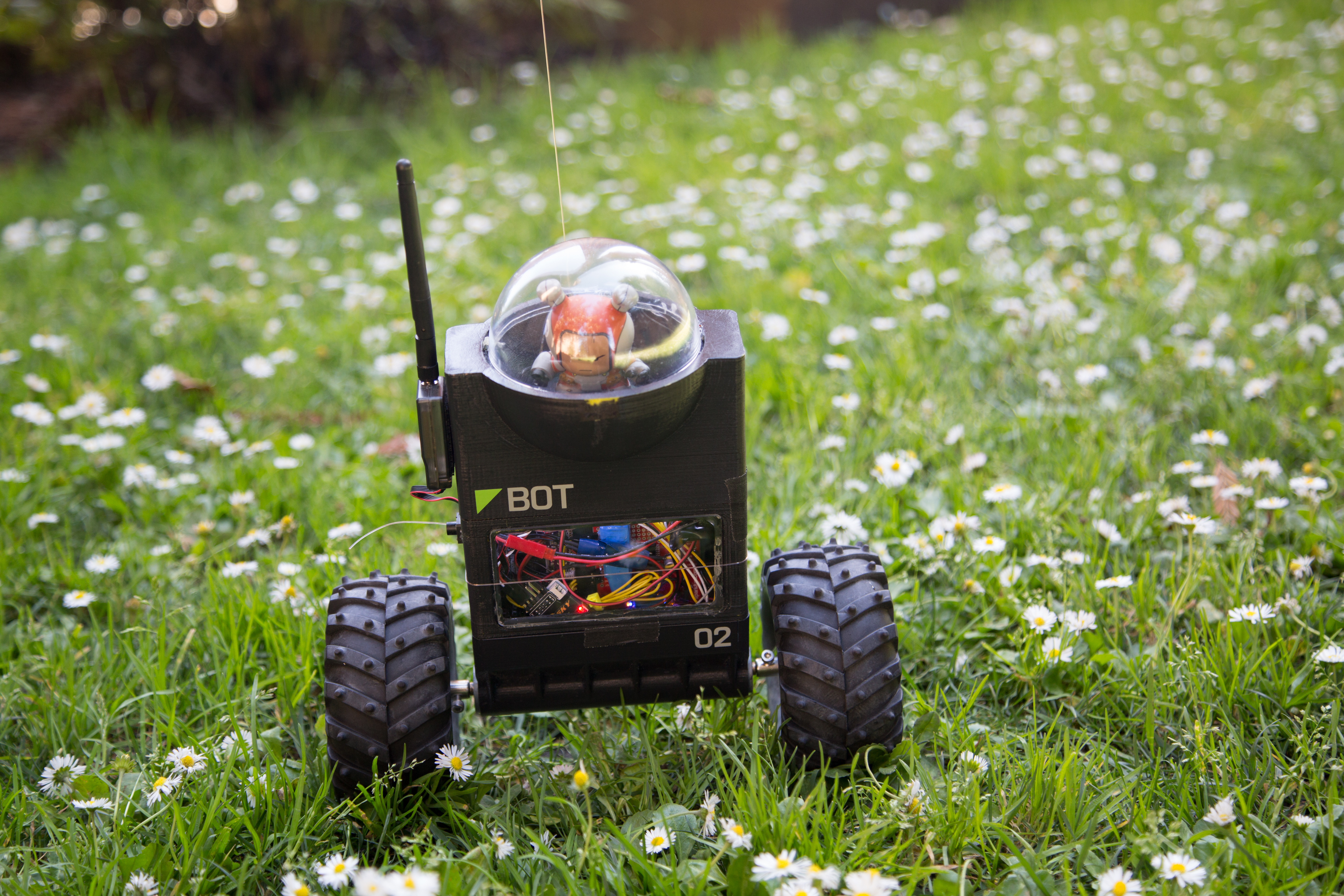


Ready to level-up your robot skills? ArduRoller is a self-balancing, inverted pendulum robot that’s also capable of autonomous navigation indoors or out. I created it as an entry for the annual SparkFun Autonomous Vehicle Competition: The goal was to create a nontraditional vehicle capable of quickly navigating an obstacle course including multiple turns, bumpy terrain, 50-gallon drums, and ramps.
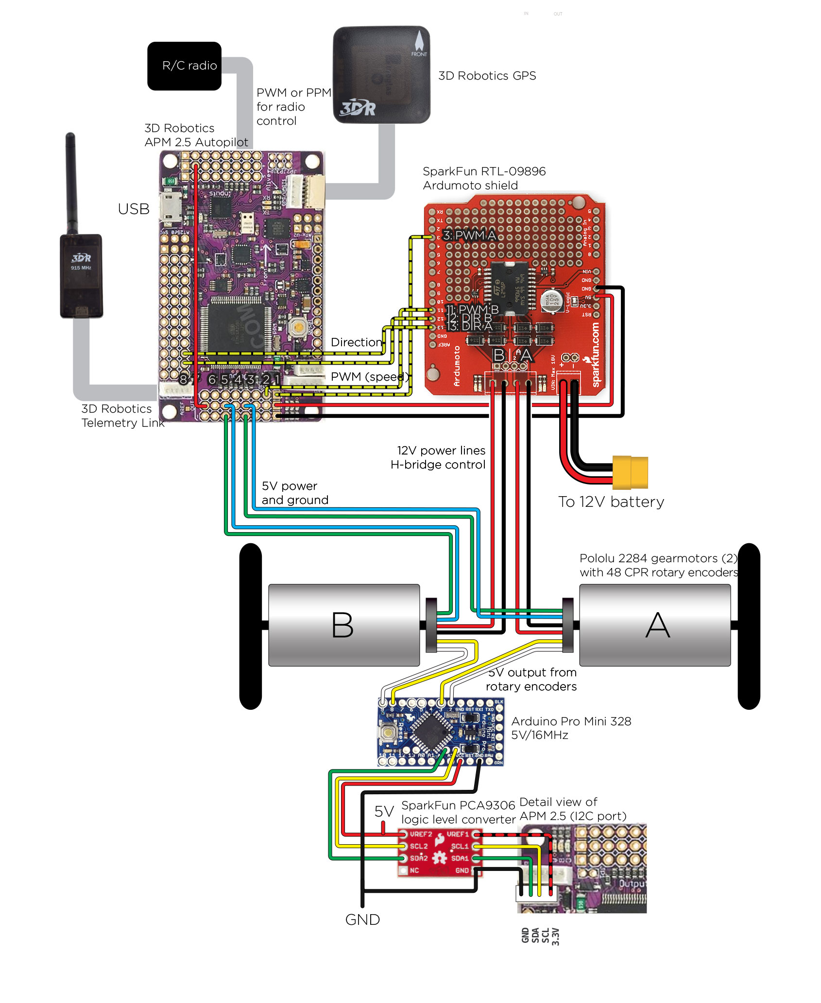
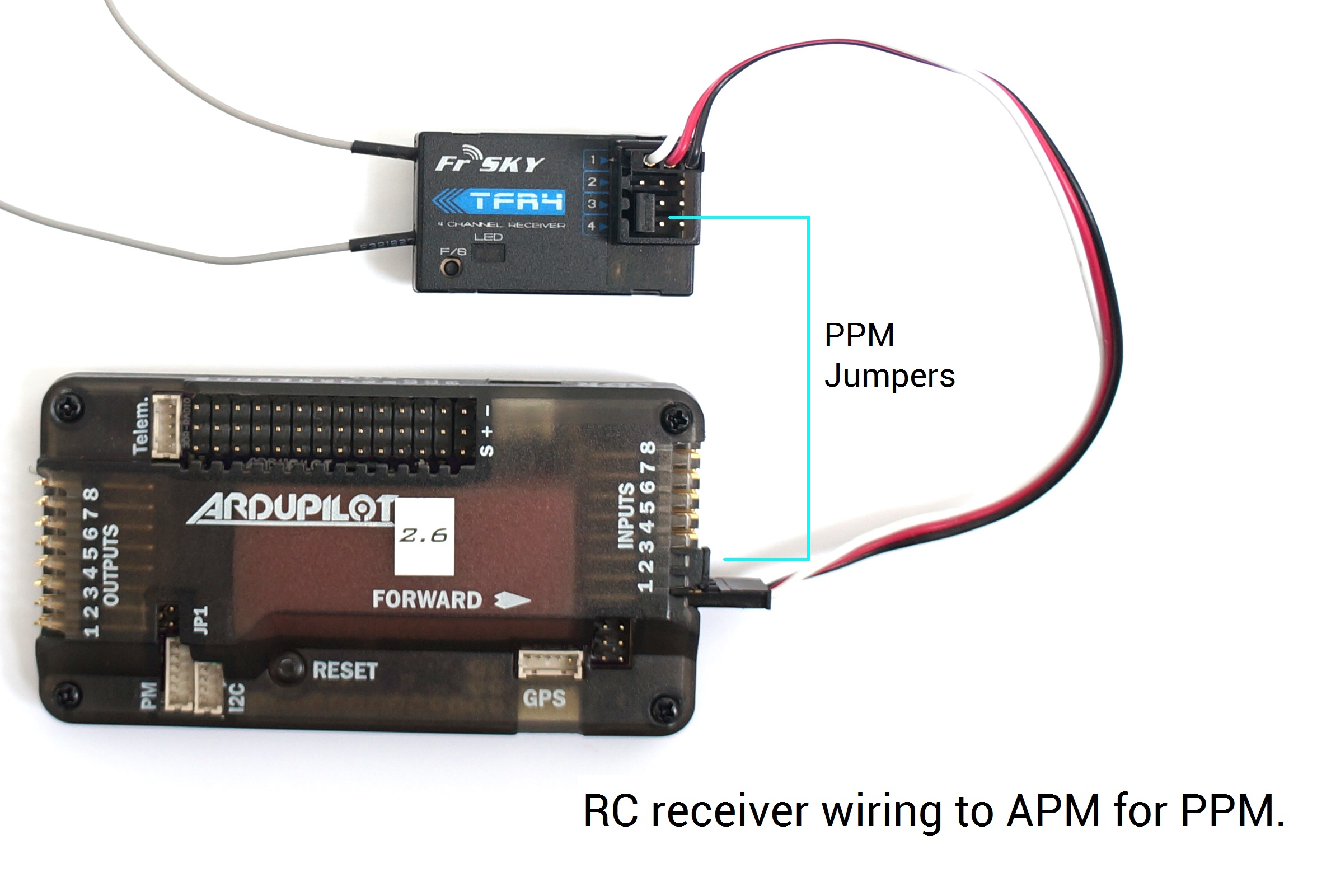
I chose a surplus APM 2.5 autopilot from 3D Robotics because it contains all the sensors needed to create the bot on a single board. The build is straightforward and the software is free and open source, based on the ArduPilot system developed by the DIY Drones community. It’s a great way to get started with autonomous robots.
The heart of a self-balancing bot is the IMU or inertial measurement unit, consisting of 3-axis rate gyros, accelerometers, and magnetometers. These 9 sensors are sampled up to 1,000 times per second and integrated with a piece of code called the DCM (direction-cosine-matrix algorithm), a mathematical filter that combines the best attributes of each sensor. The robot’s higher-level code can simply ask the DCM the angle and the rate of rotation of the bot as needed for balancing.
How to Make a Robot Balance
An inverted pendulum balance-bot is inherently unstable. Conveniently, the high center of gravity creates a large moment of inertia that slows the rate at which it will fall. We can leverage this slow fall by continually moving the wheels under the vehicle as it falls. If it leans forward, the wheels roll forward to counteract the fall.
A simple PID loop in the robot’s software is the basis of the balance control:
- The proportional term takes the angle error of the bot and sends that scaled value to the motors, to keep the wheels rolling into the fall.
- The integral term is used the same way, but is the sum of all angle errors over time and helps to cancel out center-of-gravity issues.
- The derivative term is critical. Without it, we couldn’t control acceleration.
 Make It Travel
 Make It Travel
A simplistic bot just leans into the direction of travel. This works for a while, but the bot constantly accelerates and soon falls over (A). If the bot tries to right itself, forward motion stops.
Instead we need to move forward while rolling vertically (B). The first step is to make the wheels rotate at the desired speed while leaving enough power to keep the bot balanced and perfectly upright. Next we take the velocity of the wheels and feed that forward into the desired speed. This gives the bot the ability to resist rapid changes in angle, such as a person trying to push the bot over. This algorithm was developed through observation of how people balance when being pushed. For example, a lineman in a football game throws his leg back and leans in when hit.
These two additional inputs are summed with the balancing algorithm and sent to the wheels, enabling the bot to gracefully accelerate and travel long distances.
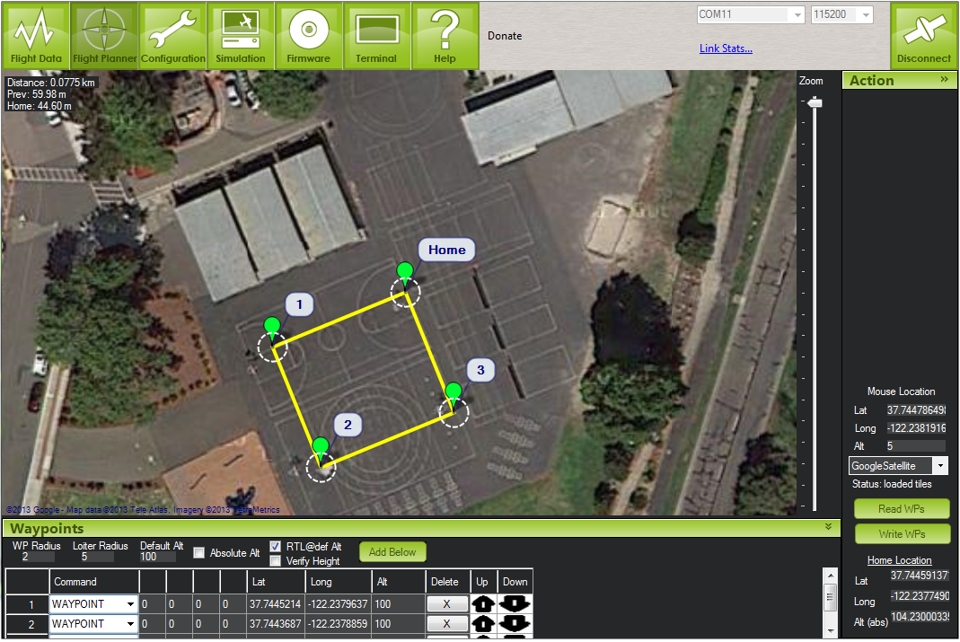
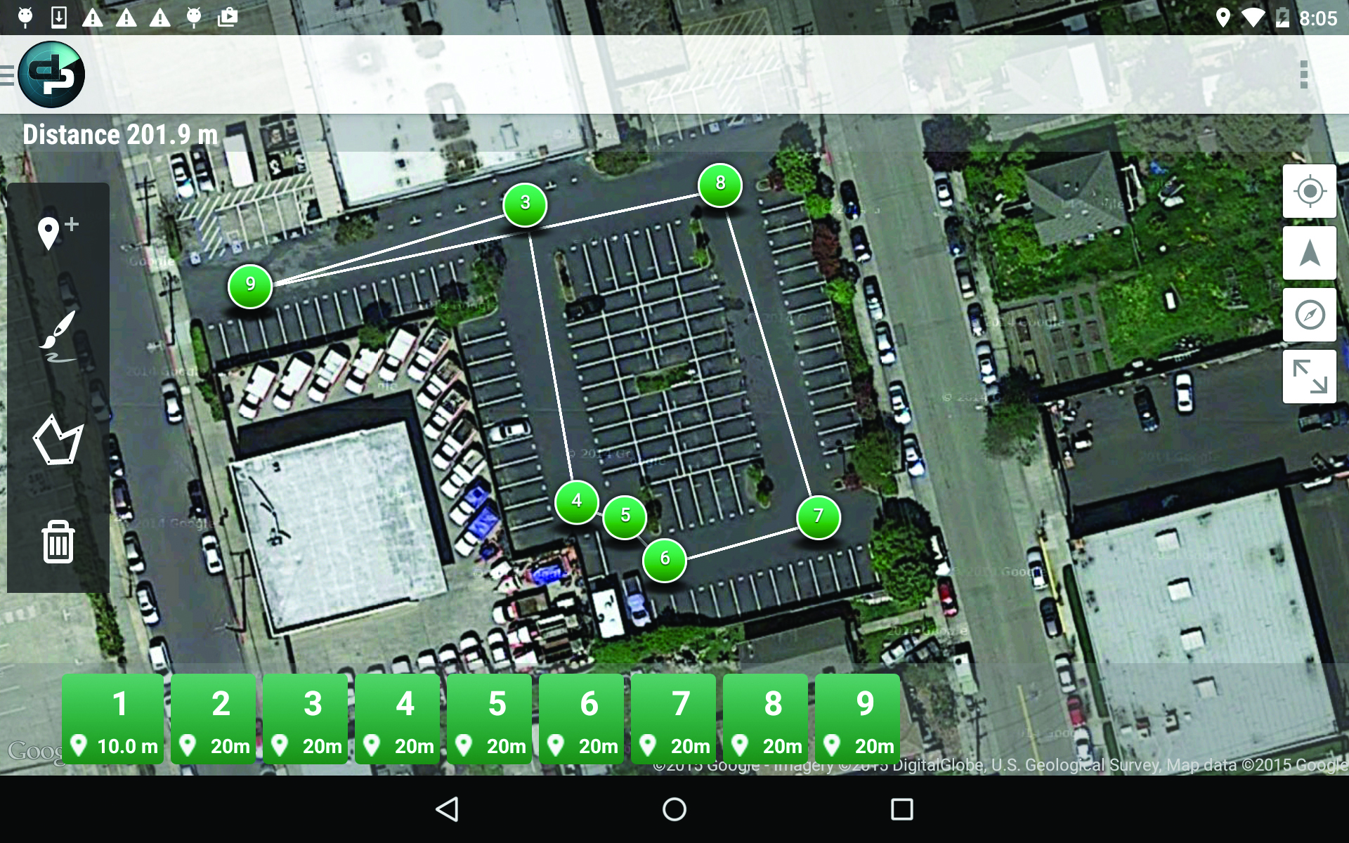
Make it Navigate
In order to make the robot navigate, we need to know precisely where it is and where it’s going. GPS is great, but only accurate to a few meters. We need far higher accuracy — down to centimeter scale.

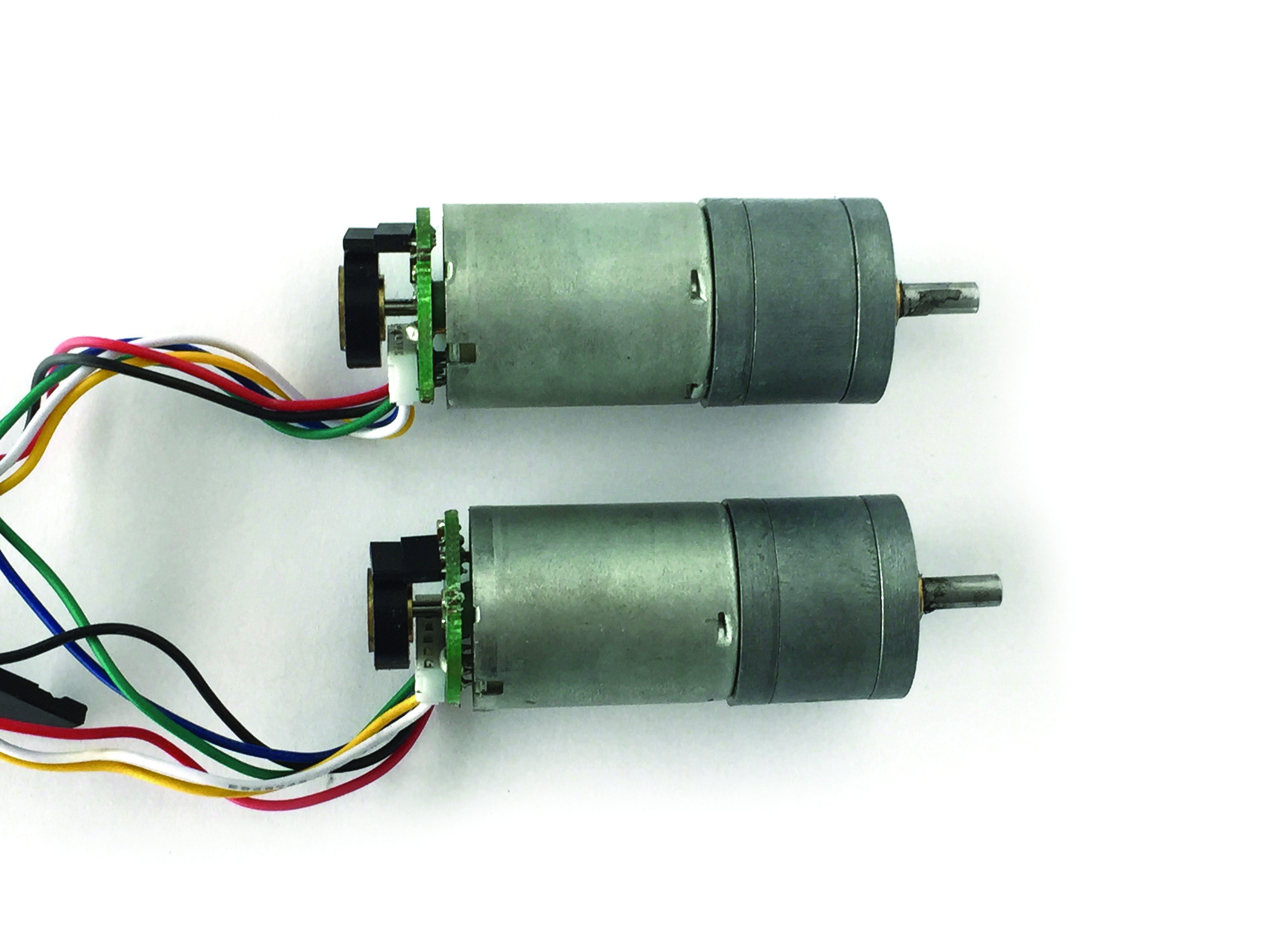
Wheel encoders allow accuracy down to millimeters and are a good complement to GPS. Motors sold by Pololu have optional Hall effect (magnetic) sensors that work like a bicycle computer: Small magnets rotate past the sensor, giving us the speed of the wheels as they rotate. An Arduino Pro Mini reads the thousands of pulses per second sent by the encoders, and relays that data to the autopilot via an I2C interface. Once you measure the diameter of the wheels, the bot will know exactly how fast and how far it has traveled. Because the bot also knows its compass heading, it can plot its precise position in 2D space. When available, GPS is used to gently nudge this solution over time to ensure that wheel slippage or other errors don’t build up and send it off course.
If the vehicle becomes stuck while roving in autopilot, it will sense the wheels have stopped. The bot will reverse course and try again, slightly to the right.
The rest of the robot’s control software, including waypoint navigation, is simply a modified version of ArduCopter, the open-source drone project that I founded 4 years ago. This allows us to leverage a large volume of work built by a community of drone enthusiasts.
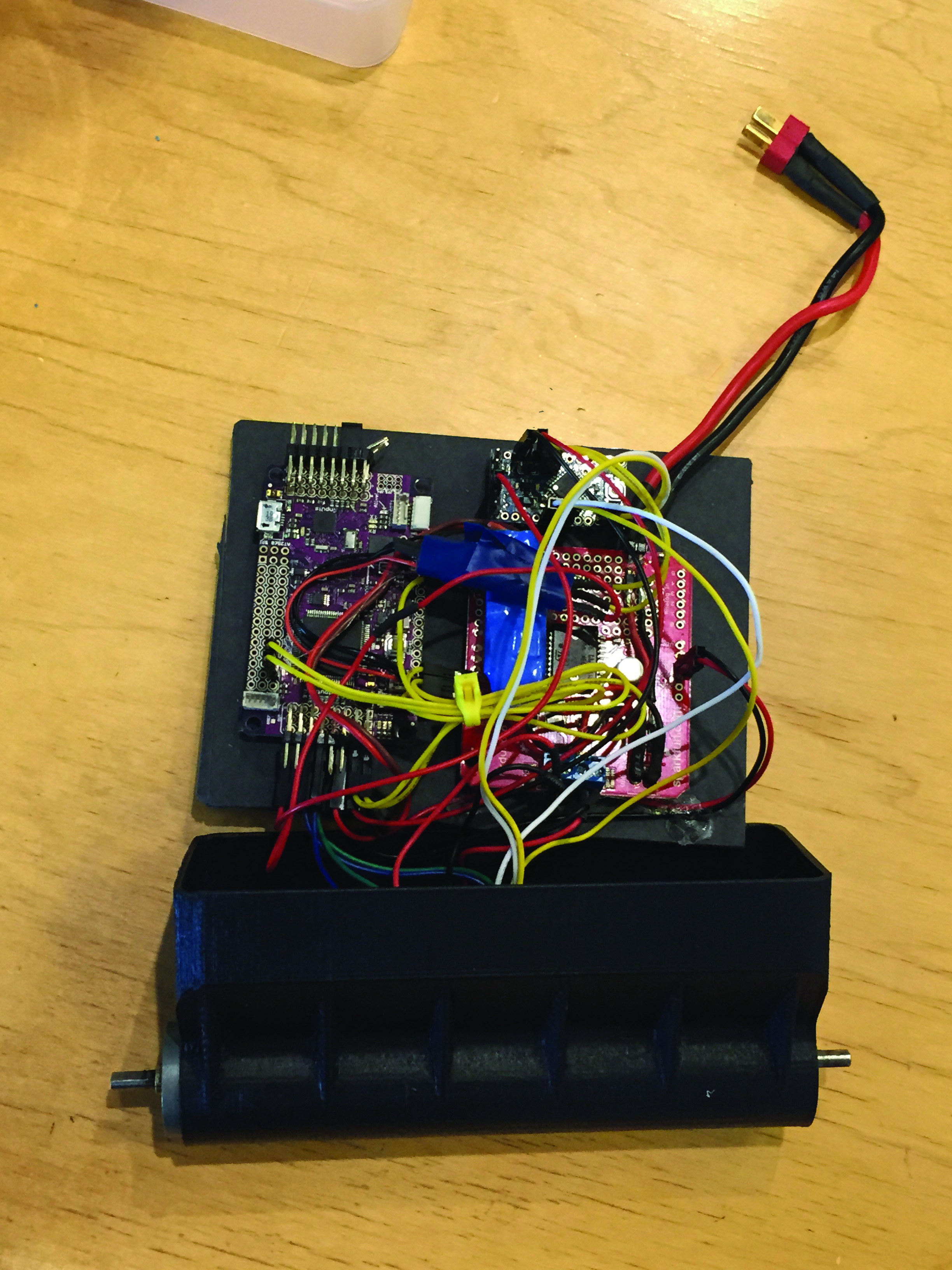
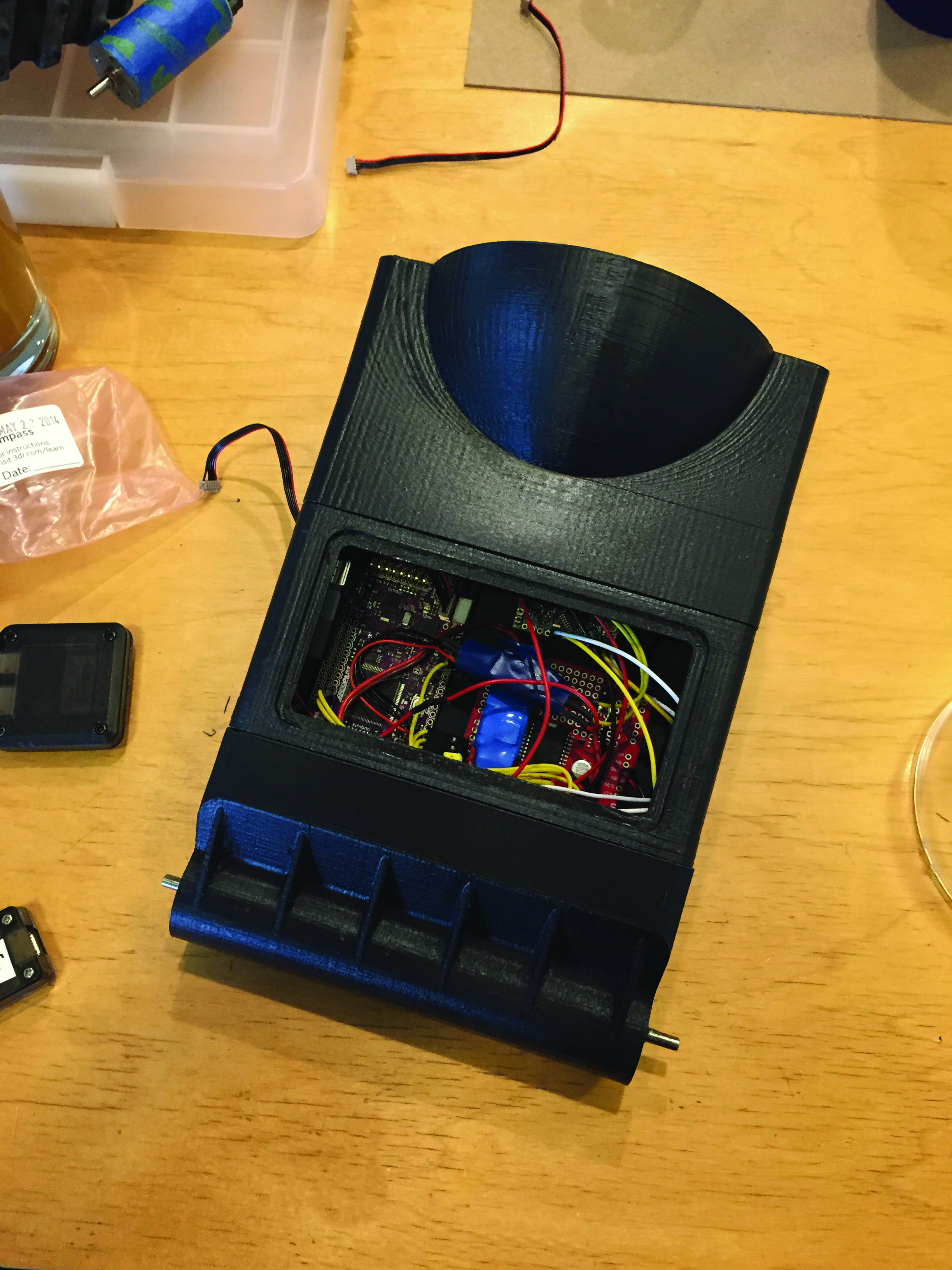
Time to make! The following project takes about 3–5 hours to complete and can cost around $400–$500.