Photo20

It’s not a complicated concept. It’s not even terribly difficult to implement. It’s just that I really don’t understand why no one produces a product like this…

I have a heated shop and a heated garage. I also live in a fairly cold climate. I don’t want to keep my garage or shop up to working temperature if I’m not actively working, but I do want to keep them at some reasonable temperature (above freezing) in the winter. I’d like to keep these areas at something like 50-55°F when unoccupied, and then heating them to 68-70°F when I’m working. I have been doing this by using standard mechanical thermostats and the process of sliding the setpoint back and forth is somewhat imprecise.

If only someone made a “dual setpoint thermostat”… I tried to find one on several occasions, but had no luck. Sure, they make smart thermostats that know when you’re physically in the space, thermostats that connect to your WiFi, thermostats that learn your habits, but nothing as simple as a thermostat with two set points. It looked like if “someone” was going to make a dual setpoint thermostat, that “someone” was going to have to be me.

Photo18

It didn’t need to be complicated. I wanted to hit one button to implement my “working temp” and have another button to invoke my “away” temp. I also needed to be able to adjust and fine tune each of the two setpoints independently. The setpoints and current operating mode (work/away) should also survive a power outage and automatically be reinstated when power returns. Each of my two thermostats would only need to control a single wall-mounted gas shop heater so a single relay contact would be perfect. This had all the attributes of a simple Arduino-based project. So off we go!

The dual setpoint thermostat uses off the shelf components whenever possible and the enclosure will be 3D printed.

We are going to use the Sparkfun RedBoard as the Arduino compatible microcontroller for this project. The specific choice of microcontroller board is not critical. However, be aware that the holes in the left side of the 3D printed enclosure are specifically designed to work with the RedBoard. If you choose to use some other Uno compatible board, you will likely have to redesign the left side panel. The rest of the RedBoard footprint matches the Uno dimensions so it’s likely that the rest of the enclosure will be just fine with any Uno clone.

Also, I chose the relay for this project because it was available from the supplier I was using for many of the other parts. While this project could be built with different relay breakout boards, be aware that if you choose to use a different relay, you will likely have to modify the enclosure design to fit a different footprint.

Photo01


How It Works

The thermostat was specifically designed so it would not need to be disassembled to mount, program, or attach the heating circuit wires. It’s also quite possible to program the thermostat (or any Arduino compatible microcontroller) without having to bring your computer or laptop next to the device. IOGEAR makes a very nice Wireless 4-Port USB Sharing Station (GUWIP204) which can be used to remotely program the device anywhere you have Wifi coverage. Once the device driver is installed, your computer will think that the remote USB ports on the GUWIP204 are actually local to your computer. Take the Wifi USB Hub to the location where your thermostat is, plug the USB cable from the thermostat into the Wifi USB Hub, power the hub, and program the device remotely.

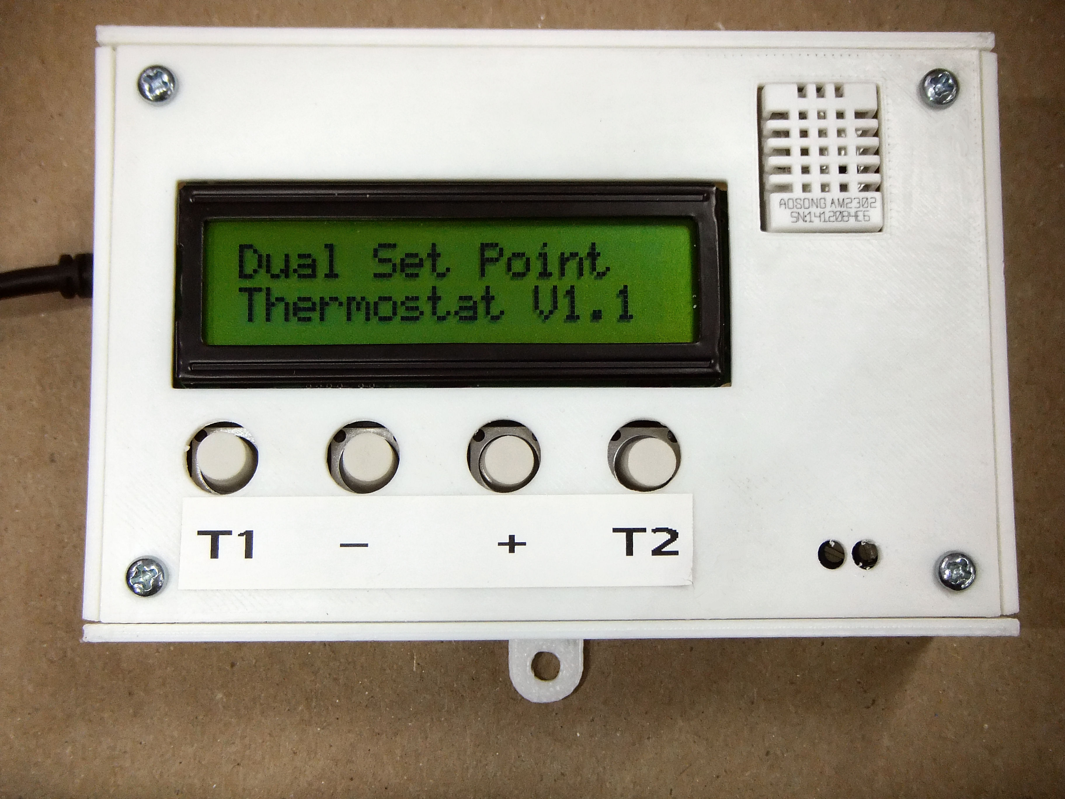
The thermostat display will tell you which temperature setting is currently active in the upper left (T1 or T2). Right below that information it will display the actual setpoint value. In the lower-right of the display you will see the actual temperature and the relative humidity (since the sensor provides it as well). In the event that heating is actually required, you will also see an asterisk in the lower middle of the display indicating that the relay is closed. The actual temperature and humidity is updated every 2½ seconds. The display will automatically illuminate for 60 seconds after any button is pressed.

Project Steps

Cut stackable heads for the microcontroller

The first thing you will notice when we put the Olimex Shield directly on top of the Microcontroller Board is that it won’t lie flat. The barrel power connector interferes with the underside of the LCD shield and keeps the pins from seating fully.

This is where the stackable headers come to the rescue. We are going to insert the headers between the boards to help separate the boards and make a nice flat, solid connection. Before we install our headers, we are going to have to do a couple of things. First, use a set of needle-nose pliers to remove the little plastic spacers on the underside of the shield pins

This will help ensure the shield fits as snugly and closely as possible to the microcontroller board. Next, cut down a couple of the stackable headers to match the shield pins. You can use a rotary cutoff tool or even a pair of diagonal cutters to do this.

Cut stackable heads for the sensor and relay

We might as well cut a couple of stackable headers to use as sockets for the sensor and relay as well. You will need three 4-place headers, one 3-place header, and two 2-place headers. While you are cutting down the original 6-place headers, try and preserve a couple of the internal pins so they can be used as signal connectors on the relay and sensor harness.

Shorten the shield pins

Once you have the headers cut, install them on the shield and then mate the shield to the microcontroller board. You will note that, when completely seated, there is a little extra pin length both above and below the stackable headers.

Separate the boards, remove the headers, and shorten the shield pins to take up the upper “slack”. Similarly, cut the stackable headers to remove the lower “slack”. Reassemble the LCD shield, modified stackable headers, and the microcontroller to confirm a firm, flush fit.

If you look at our assembly from the side, you will note that there is a long line of pins soldered through the LCD circuit board.

These pins need to be shortened or they will interfere with the fit of the enclosure cover. Using the rotary tool, or a very small pair of diagonal cutters, sand and cut these pins down closer to the PCB.

Desolder (or cover) the LEDs on the LCD Sheild

Once I completed my first prototype, I noted that there was a lot of light emanating from within the enclosure. There are a total of three LEDs in this project which will illuminate when the thermostat is turned on. While the power LED on the microcontroller board is sufficiently buried to be hidden, the power LEDs on the LCD Shield and Relay can cause the enclosure to glow from within. While you can simply de-solder the LED on the LCD Shield, I noted that doing this on the relay will cause it to stop functioning. I have also heard that you can simply coat the offending LED’s with black nail polish to hide the illumination, but, sadly, I don’t have any. De-solder (or cover) the power LED on the LCD Shield.

De-solder AND BRIDGE the LED pads (or cover the LED) on the power relay.

Prepare the wiring harness

Next, we are going to make our wiring harness. I am using a scrap of Cat5E network cable but you can use any small gauge, solid stranded wire to do this. Since I’m using Cat5E, I’ve selected the orange wire for sensor/relay 5V power supply, green for sensor/relay ground, blue for the relay signal, and brown for the sensor signal. Since both the sensor and the relay require both a power supply and a ground, the 5v and ground wires will have a single feed and a dual connections (a “Y” shape). The relay and sensor signal wires will only require a single connection on both ends. Total length for each of the wires needs to be no more than a couple of inches. Solder the “Y” connection on the power and ground wires and cover with heat shrink tubing. Solder a spare stackable header pin (freed when cutting the headers) on the end of the relay and sensor signal wires. Protect the signal wire pins with heat shrink tubing.

Using modified stackable headers makes some really nice connector sockets for our sensor and relay instead of soldering directly to the devices. This makes it very easy to change out the relay or sensor should one become defective. The modified stackable header also makes a very nice location to solder the 10K pull-up resistor required by the DHT22 sensor. First cut off the third leg of the header as that pin is not used or required by the sensor. Then, take your small 10K resistor and wrap each leg around one of the two nearby legs on the header using a small needle nose plier. Wrapping the legs will make it very easy to solder the resistor in place and will ensure it doesn’t come free when we solder the wires from the harness. Once the resistor legs are wrapped, solder the resistor in place and trim the excess wire with a small set of diagonal cutters.

Solder the wiring harness

Now we are going to solder together the wiring harness. Be sure to slide some heat shrink tubing onto the wires BEFORE you solder them to the modified headers. Keep the heat shrink tubing well away from the connection while you are soldering to prevent “premature shrinkulation”. Solder one of the 5V power wires (orange) to the outside connector of the sensor connector with the resistor. The sensor signal wire (brown) should be soldered to the inside connector with the resistor. A ground wire (green) should be soldered to the other side of the sensor connector next to the empty pin. The relay signal wire (blue) goes to one side of the modified 3-pin header. The remaining 5V power wire (orange) goes to the center pin of the relay connector. The remaining ground wire (green) goes to the other side of the relay connector. Once all solder connections are completed, slide the heat shrink tubing in place and heat to shrink.

Next, solder the loose 5V power and ground wires to connectors on the LCD Shield. You could choose to do this to the microcontroller board instead, but since we’ve already started modifying the shield, I chose to keep my microcontroller “unharmed”. While there are six holes in the LCD Shield PCB below the third button (from the left), only 4 pins are actually populated. We are going to solder the harness ground wire (green) to the pin on the right, and the 5V harness wire to the pin second from the right. Take a look at the attached photo or simply trace the 5V and ground connections up from the microcontroller to confirm the placement.

Print the enclosure

Print the enclosure. I used white ABS filament from Hatchbox in my Makerbot Replicator 2X to do this. I used TurboCad 3D to do the enclosure design, exported it to *.STL format, and loaded it into Makeware to generate the *.X3G print files. (Hatchbox ABS filament, particularly White filament, likes to be printed at about 220°C rather than the Makerware default of 230°C). The base of the enclosure holds the mounting pads for the microcontroller board and the relay. The base also has a small shelf to hold the sensor and two holes in the side to allow the relay control wires to be passed through the enclosure. The left panel for the enclosure has a couple of access holes for power and programming and also a little shelf to support the left side of the LCD panel and to keep it from tipping off the microcontroller board when buttons are pressed. The cover for the enclosure not only has the required holes for the LCD Panel, buttons, and sensor, but also has a couple of holes to allow adjustment of the relay screws for control wires as they are inserted to the box. A couple of tabs complete the enclosure so it can be attached to the wall or even just a bare 2×4. You can download the associated TCW, DWG, STL, and X3G files in a single archive from the Haute Solutions web site.

Putting everything in the enclosure

Using four #4×⅜ screws, attach the shield to the enclosure first. Attach the sensor signal wire (brown) to pin #2 on the microcontroller board. Attach the relay signal wire (blue) to pin #3. Note that I have twisted the wires in my harness to make routing and assembly a bit easier.

Place the modified “spacing” headers onto the LCD shield. Then bend the relay/sensor signal pins slightly outboard to clear the LCD shield as you align it and seat it on top of the microcontroller board. The relay can be installed using only two screws and the sensor requires only one. Attach the wire harness to the sensor and relay. The resistor on the sensor should go to the left when viewed from the front. The signal wire (blue) on the relay should go toward the right side when viewed from the front.

Place the left side panel carefully ensuring that the little shelf properly supports the LCD shield. Attach the right side, drop on the cover, and secure the sides and cover with four more screws. Label the buttons with a label maker (or permanent marker) to indicate the following left to right “T1”, “-“ (minus), “+” (plus), and “T2”.

Download the code

Download the latest version of the Dual Setpoint Thermostat code from the Haute Solutions website. You will also need the Olimex LCD Library and Ladyada’s DHT library. Extract the libraries to your personal “DocumentsArduinoLibraries” folder, load up the Arduino programming environment, and program the Thermostat. When you start up your thermostat, you should see the welcome message and version of the thermostat code.

Once the thermostat has completed its startup process, you should see the actual setpoint and temp/rh in the display.

Since we don’t want the digital thermostat turning on/off every 2½ seconds during threshold conditions, we have programmed in some digital hysteresis. A value of 2°F has been programmed in as a temperature “overshoot value”. So, if you set a desired temperature of 70°F, and the temp falls to 69°F, then the heat will come on and heat to 72°F before it shuts off. This can be adjusted using the variable TOVERSHOOT in the program code.

The code has also been designed to minimize continuous update of the EEPROM memory in the microcontroller. (EEPROM memory has a large, but finite, number of update cycles.) Rather than updating the EEPROM each time a button is pressed, we only update it after something has been changed and 60 seconds of idle time has elapsed. This prevents needless updates as temperatures are incremented or decremented. The currently active setpoint (T1/T2) is also stored in EEPROM memory as well as the associated setpoints so the thermostat will properly return to its last operating state after a power outage.

Set and mount your new dual setpoint thermostat

By default, the lower setpoint  (T1) will be pre-set at 45°F. The upper setpoint (T2) will be pre-set to 90°F. These are actually the Min/Max values for the thermostat as programmed. We don’t want the temps to fall too close to freezing and we don’t want to burn the place down trying to heat it. When the thermostat is first powered up, the lower setpoint (T1) will be active. Use the minus (-) and plus (+) buttons to adjust T1 to your desired lower (away) setpoint. Note that you can’t adjust below the min (45°F) or above the max (90°F) limits. Once you have the T1 temp set, press the T2 button and use plus/minus to adjust your desired upper (home) temperature. Both of these setpoints will be remembered if the thermostat loses power. (They are stored in the microcontroller EEPROM.) Once you have the setpoints adjusted to the desired settings, simply hit T1 anytime you want to invoke the lower setting and T2 to invoke the upper setting! Going to be working in the shop: “T2”! Done working for today: “T1”! It’s that simple!

Mount the thermostat to the wall or other suitable surface. There are two small holes in the thermostat cover which will accept a small flat bladed screwdriver to loosen/tighten the associated screws on the relay. The holes should be directly above the NO (Normally Open) terminals on the relay. Loosen each screw, insert a wire from your heating circuit through the corresponding hole in the side of the enclosure, and tighten. The thermostat can be powered via either the USB port or the barrel connector.