As an active amateur music maker who likes to use technology with his art (thus combining two hobbies) I have been making tech to help me have more fun on stage. This has led to a programmable pedal board that connects to my digital mixer via WiFi and a multi-track recorder to automatically record our rehearsals. Both of those builds were based on the Raspberry Pi and required a lot of python code to make the solutions to work the way I needed.

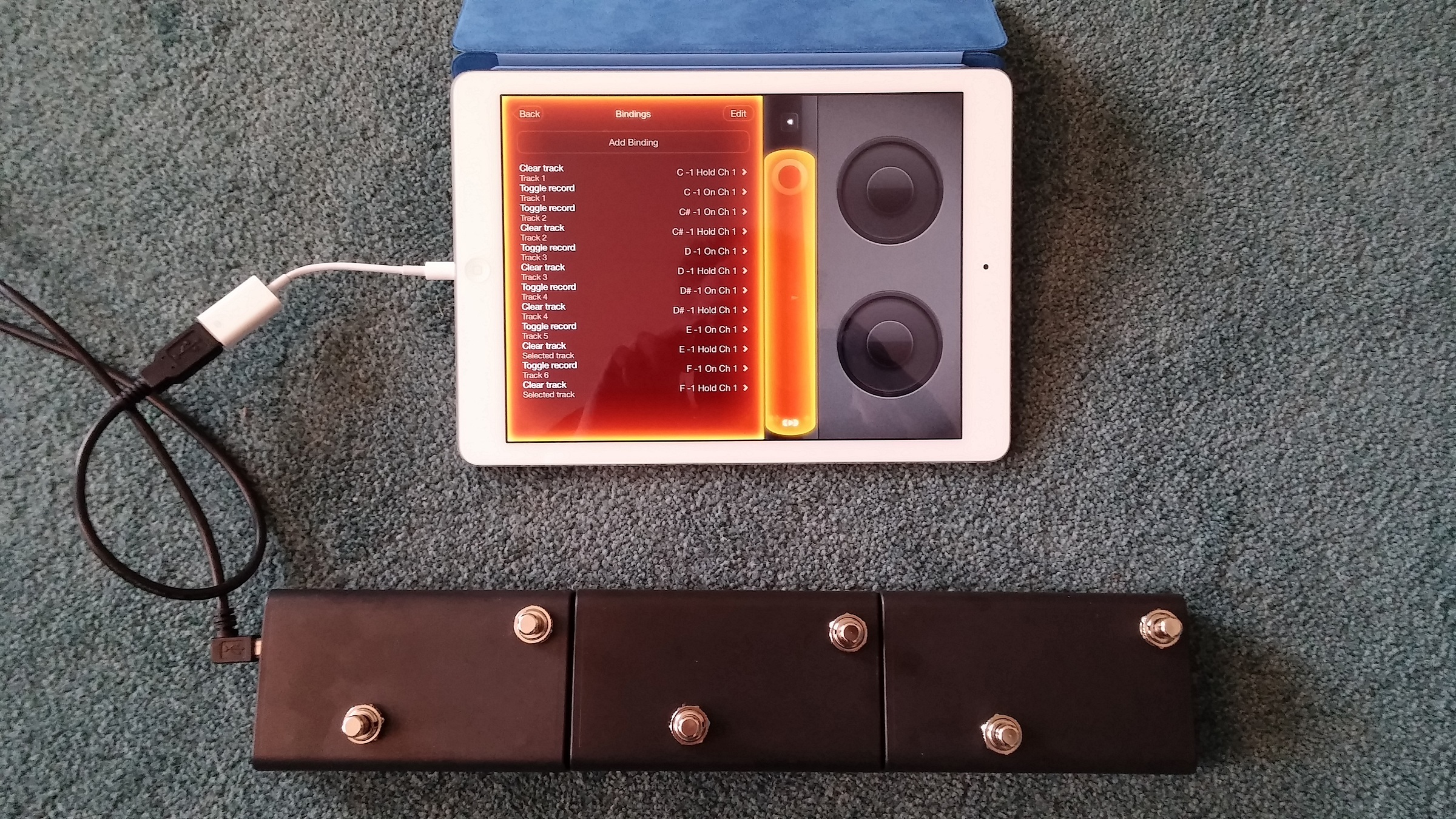
The goal of this build was to get a cheap foot pedal bar that allows me to control apps such as Loopy HD hands-free. This allows me as an artist to keep eye-contact with the audience, otherwise I would need to look at the iPad all the time and risk getting sucked into looking at the screen rather than the people who came out so see me.

Pedal boards like Behringer’s FCB1010 are really useful for certain uses and affordable (I own one), but also very bulky to carry around. I needed something smaller and simpler for this purpose.

image03

When browsing on the web I ran across some articles online that offered the parts of what I needed. This project was a quick combination of these parts to solve my problem. Hopefully it solves yours too.

The components

The iPad is a great platform for a musician/singer who needs effects at their fingertips. The audio processing in an iPad is speedy and this has led to a number of very useful apps for musicians, such as Loopy HD for looping and TC-Helicon’s VoiceRack FX for vocal effects. These apps can not only be controlled via the touchscreen but will also take MIDI commands.

The rather misnamed iPad Camera adapter turns the iPad’s lightning interface into a USB master. So any USB-class compliant device is suddenly recognised as a device on your i-device. This can be a USB-Audio interface or a USB MIDI interface, or with a USB hub both. More on the latter use case at the end of the article.

For the smarts of this build I decided to use an Arduino UNO as it has a useful party-trick: Its USB interface can be reprogrammed to be a USB MIDI HID device instead of the usual serial device. That makes it a plug-and play solution for my purposes.
This trick only works with the “real” Arduino UNO or an “expensive” Chinese version that has a 8u2 or 16u2 USB interface. The CH340 USB adapter on the cheaper Arduinos will not do this!

Next to the Arduino, very little is needed. For each button you need: just one foot switch, one capacitor, and a resistor. This build easily scales to 11 buttons with no thought. With some effort you can even add more, if you need that.

I spent some time searching for the right case for this build but found none that met my needs. I opted to use a couple of Strapuboxes from Conrad and fix them together. Any other cases you can lay your hands on will do just as well.

This build took me less than a day (not counting the drying time of the glue) and approximately €20 ($22.50).

Project Steps

The hardware build

For the hardware I started start with the electronics. From earlier builds I found that the foot buttons need some debouncing in both hard- and software. So I bridged the buttons with the capacitors. The resistors are connected to a pull down resistor.

image04

The top-side of the boxes are drilled with holes for the buttons and that can be wired up.

image05image02

This can be done for up to 12 buttons easily, I needed just 6. You see the connections of the cables to the buttons in digital inputs 2-7. I achieved a good connection by simply getting a coating of solder on the stripped cables and pressing them into the connector. For expansion, the software will pick up additional buttons in connections 8-13 with no modification.

The bottom-side of the boxes gave some headache. The boxes turn out not to have straight sides but slightly slanted ones. If you connect these close-up by screwing or directly gluing them together you’d end up with a banana-shape rather than a flat board.
On making space for the cables that had to run through the length of the boxes I found that one can easily melt them together with a hot knife. Furthermore some glue between the wedges on the bottom side ensured a firm bond while retaining the flat bottom across all 3 boxes. I used a piece of (black) duct tape to keep them tight for the drying time of the glue. The duct tape also seems to work well to keep the resulting bar from sliding on slick floors so I am keeping it under the finished device. During the drying time of the glue I kept them flat with the use of some make-shift weights (see picture).

While the glue is drying, the software build can be done.

image00

Software

Buttons to Arduino
The software comes from this hardware to MIDI project from Instructables. I just removed the code for the analog inputs and changed the serial speed to the MIDI default rate of 31250 for maximum compatibility. I also turned the software for the pull-down resistors, so a button being pressed leads to the digital input going to 1. The resulting code is in Annex A below.

Turning on the debugging in the code shows that all the buttons work on the serial output. Then turn off the DEBUG again and send the sketch to the Arduino again.

Arduino to MIDI
Next convert the UNO’s 16u2 to become a MIDI HID.

This description explains how the Arduino USB interface can be reprogrammed. However, I did not have the right programmer hardware and I could not get the software to work readily.

So I used the firmware file from HIDUINO  and the programming steps from here. This worked great.

image01

WARNING: Make sure the hardware has been shown to work as flashing a new sketch into your Arduino now requires you to either flash the interface back to serial mode or connect a programmer on the connector on the Arduino!

I temporarily connected a button to the reset and ground pins shown in the figure to the right. Briefly pressed that button and executed on my linux box:

sudo dfu-programmer atmega16u2 flash arduino_midi.hex

Followed by:

sudo dfu-programmer atmega16u2 reset

I unplugged the USB link from the the arduino, re-inserted it and tada-the device was recognized as a USB MIDI device! A quick check with a MIDI trace program showed that all the buttons were registered as MIDI events as planned.

Connecting to the i-device
You can use the Apple camera adapter to connect the Arduino’s USB lead to the iPad/iPhone/iPod of your choosing. Loopy and other apps will recognize it as arduino_midi.

Next LoopyHD can be taught how to respond to the events. To this end you will go to the Settings screen on Loopy and select the arduino_midi input. Here you can add new bindings of a button press (or hold) to an action in Loopy.

When you add the binding you need to select:
The event, so press the button you wish to bind
The action, so select something suitable from the plethora of options.
The track, is it the current track or a specific one?

You can do this for all your buttons and experiment. Loopy has so many options, you will need to experiment a bit to find out which binding will work for you.

On iPad, LoopyHD and USB hubs
I had some problems getting both my audio interface (into the mixing desk) and the USB MIDI bar I just built to work together nicely. The input of both audio and MIDI worked great. However, with the USB hub in between, the audio out from Loopy did not work. After some prodding and firing up another app that just produced audio, it suddenly worked. So I can recommend that you find an order for plugging in and starting up the app that works for you.

Enjoy your music making!
Download the Annex sketch here