What do you do when you want a CNC machine, but don’t have the room or the funds for a massive professional machine to build your custom parts? I found myself in the same dilemma, so I chose to scale down my purchase and invest in a manual mill that I could eventually convert to a CNC machine.

Before purchasing my X2 Mini Mill from LittleMachineShop.com I did some research to investigate what it would take to make the switch from a manual mill to a complete 3-axis computer numerically controlled milling machine. These small hobbyist mills are manufactured in China and Taiwan, and then shipped to companies like Harbor Freight, Grizzly and Micro-Mark who paint them various colors and sell them under different names. Since the basic foundation is all the same, a small community has formed around this popular mini mill platform to share ideas and hacks. When opting to convert to CNC, there are numerous kits and conversion designs to choose from. These options range from simple PDFs with diagrams and schematics to high-precision hardware and electronics bundles.

CNC Fusion is a small company that machines high quality conversion parts made from 6061 aluminium stock. The company started in 2004 when Michael Rodgers, a machinist by trade, wanted to build a CNC machine but realized that he could not build the parts he designed without first owning a CNC machine.

That initial desire has led Michael to design and fabricate CNC conversion kits for small manual mills and lathes, and now his kits are sold around the globe (40% of CNC Fusion production is shipped to overseas customers). The household garage has been converted into a machine shop where Michael machines the majority of the kit components using a huge five axis CNC mill while wife Sharron runs the massive CNC lathe to machine the ends of the ball screw threads sold with their kits.

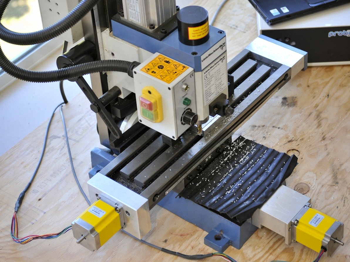
The X2 Mini Mill kit is the most popular from CNC Fusion, primarily because the mini mill platform is considered a great tool at a modest price for hobbyists. With the X2 Mini-Mill CNC kit #2 all the new upgrade parts bolt to existing features and you replace the factory lead screw with high-precision ball screws and new motor mount adapters to accept NEMA 23 stepper motors. The hardware installation is very straightforward and requires the disassembly of the X and Y axes before reinstalling the ball screws. You will also need to drill two holes into the central column of the mill to install the Z-axis ball screw hardware. Besides this step, the entire process is completely reversible in case you ever decide to switch back to manual machining (but honestly, why would you?).

I will provide steps for setting up the electrical components and required software in a separate tutorial. This project will only cover the physical hardware conversion.

Project Steps

Remove the Table

Clean the mill to remove any dirt and loose debris. Use a vacuum for any large chips or metal shavings, and wipe down the surfaces with a rag soaked in acetone or alcohol to remove grease. Start by removing the Y-axis hand wheel and keyway.

Remove the black corrugated plastic front and back Y-axis covers that protect the ways from debris and scraps of material. Lift the corner of the cover and use a Philips screw driver to remove the two screws bolted to the saddle.

Raise the corrugated plastic and reveal the second pair of screws located on the handle block of the Y-axis hand wheel.

Keep all these parts in a safe place. Once the CNC conversion is complete you will want to re-install these covers.

Remove the Y axis handle block using a 5mm hex key. Keep the original Y axis cap screws; you will use them later. Remove the Y-axis feed screw and the half nut.

Remove the cap screw and washer threaded into the end of the Y axis feed screw.

Hold onto the half nut in one hand and manually rotate the feed screw clockwise until the half nut falls off the threads.

Remove the small plate on the left side of the table using a 5mm Allen wrench (opposite the X axis hand wheel). You will not need the two screws that hold this plate in place.

Remove the X-axis hand wheel and keyway on the right side of the table and set the hand wheel aside for now.

Unscrew the two cap screws that secure the thrust plate to the right side of the table. Let the thrust plate hang freely.

Loosen the four X-axis gib setscrews and carefully slide the table off the X-axis. Set the table aside for now on a clean surface.

With the table removed use your hands to wiggle the thrust bearing plate back and forth until it becomes loose, then slide the plate off the end of X axis lead screw.

Carefully set the thrust bearing plate and bearing aside for now. Once the new X axis ballscrew has been installed, you will reattach the thrust bearing plate back onto the right side of the table.

Loosen the X- and Y-axis brake handles located on the front and right side on the saddle. The handles are spring loaded. To loosen them pull the handle straight out and use a Philips screw driver to loosen the screws. (These were removed in the following images, but this is not necessary.)

To remove the X-axis leadscrew and half nut, loosen the two set screws on the right side of the saddle. These small set screws lock the X axis half nut in place.

After loosening the set screws, lift the X axis leadscrew straight up and off the saddle.

The saddle of your mill should now look like this, with the X- and Y-axis lead screws and the table completely removed.

Install the Y Axis

The Y-axis motor mount, motor coupling, and ball screw come pre-assembled in the kit. However, you need to separate the components in order to install the ball screw.

Start by loosening the motor coupling setscrew using a 3/16″ hex key so that you can slide the coupling off the end of the ball screw. Remove the locking collar and slide the ball screw out of the bearing.

Push the saddle back toward the column as far as possible. Lay your mill on its backside. From underneath the mill, feed the Y axis ball screw through the hole in the base, while at the same time inserting the aluminum ball nut mount into the slot that held the original half nut.

At first it seems like the ball screw is too long and that the you will not be able to properly angle the ball screw within the limited space. Be patient; eventually the ball screw falls into place and the aluminum ball nut is seated properly.

Use an Allen wrench to snug up the locking screw that secured the original brass nut. This will hold the ball screw in place while you stand your mill back up. Stand the mill upright; have a friend help to gently set the base down.

Slide the saddle forward, so that the ball screw is now sticking out the hole in the base far enough to slide the Y-axis motor mount onto the end of the ball screw.

Re-assemble the Y-axis motor mount and motor coupling at the end of the ball screw. Be sure to get the collar tight against the bearings. Push the saddle back so the motor mount is against the base, and screw two 6mm cap screws into place.

It is easier to access the two 6mm cap screws for the motor mount if you remove the front plate that is bolted to the main body of the motor mount via four small cap screws.

This step is not advised, and should only be used when all else fails

The collar that sits tight against the bearing uses a special spanner wrench. If you do not have this specialty tool, it is still possible to tighten the collar against the bearing. However, the technique described here is not recommended.

Use two channel locks or vise grips to clamp down on the end of the ball screw and the collar. Be careful not to damage the threads!

The same technique can be used in a later step when tightening the locking collar on the X-axis ball screw.

If this is not done carefully it can cause serious damage to the ends of the ball screws and jeopardize the integrity of the high-precision ground ball screws.

At this point, you will want to loosen the locking screw that secures the aluminum ball nut mount (the cap screw in the middle of the saddle that you previously tightened when the mill was on its back side). Turn the ball screw by hand until the saddle is almost all the way forward, leaving just enough room for the Allen wrench to fit between the Y axis motor mount and the saddle.

Now you are ready to fine tune the Y axis. You do not want to fine tune the Y axis with the saddle pushed back towards the column because the back end of the ball screw is unsupported and able to wobble ever so slightly. When fine tuning the axis you want to get the saddle as close as possible to the motor mount where the ball screw is supported by the bearing assembly. Snug up the locking screw one more time and test to see if there is any slipping or binding.

If you feel any backlash when you manually rotate the ball screw this indicates that you need to tighten the locking screw. If you feel binding or the Y axis does not move easily when you manually rotate the ball screw, you will need to loosen the locking screw ever so slightly. Repeat this process until the Y axis has minimal backlash and can slide freely over the ways.

It is never a good idea to move the saddle without proper lubrication. Add a bit of oil to the ways during this fine tuning to ensure proper movement.

Install the X Axis

Install the X-axis ball screw. Note that the ball nut is on the right-hand side of the mill.

Carefully re-install the table. Do not tighten the gibs yet; leave them loose for fine tuning later on. Slide the table to the left so that the ball screw is sticking out on the right hand side.

You will notice that the X-axis ball screw is longer than the stock lead screw. This is done to add extra room under the table for the larger ball nut. In order to reattach the original thrust plate onto the end of the ball screw, you will need to attach the X-axis adapter block between the right side of the table and the original thrust bearing plate.

Hold the X axis adapter block and thrust plate against the end of the table with one hand and secure the longer 6mm cap screws in place. Finish the right side of the assembly by threading the locking collar onto the end of the ball screw and tightening the collar against the bearing.

The second image shows the locking collar already installed at the end of the ball screw. This was done by mistake when we accidentally installed the thrust bearing plate to the end of the table without first adding the X-axis adapter block. If this happens to you, do not worry; it is a simple fix. Just unscrew the cap screws and slide the table over to the left so that there is enough room to insert the adapter block. Use the long 6mm cap screws to secure the entire assembly to the end of the table. Problem solved.

Remove any dirt of grease from the left end of the table and clean the internal threads if needed.

The motor coupling came preattached to the end of the ball screw. Remove the motor coupling from the end of the ball screw and install it onto the shaft of the X-axis stepper motor. Be sure to tighten the set screw that secures the coupling to the shaft of the motor.

Mount the X-axis stepper motor to the X-axis motor mount using four 6mm cap screws. Since the motor coupling extends beyond the width of the motor mount, you can use the Y- and Z-axis stepper motors as risers while you tighten the cap screws for the X axis.

Install the X axis motor and motor mount to the left end of the table being careful to align the motor coupling with the end of the ball screw. Use two 6mm cap screws to bolt the motor mount to the left end of the table using the existing threaded holes.

Tighten the second set screw on the X axis motor coupling to secure the coupling to the end of the ball screw.

If you have not done so already, install the Y axis stepper motor and motor mount.

There is no need to remove the motor coupling from the end of the Y axis ball screw. The Y axis motor mount has plenty of room underneath to access the motor coupling set screws using a long Allen key.

Snug up the two set screws on the right side of the saddle, underneath the table, that held the original brass nut in place. Not tight, just snug. We will fine tune this in a following step.

Removing the Factory Z Axis Components

Remove the Z-axis fine feed and spoked handle. Use a Phillips screwdriver to unscrew the metal cover that protects the linkage for the fine feed.

Use a pair of needle-nose pliers to remove the C-clip that secures the spoke handle to the shaft. Don’t worry if you bend or break the C-clip; you will not need it.

Save the Z-axis fine-feed dial. It can be attached to the end of the Z-axis stepper motor in case you ever want to manually move the Z axis (this can only be done when there is no power to the motor!).

With the spoke handle removed, carefully pull out the splined shaft that engages the rack.

Use the Z gib lock to make sure the head doesn’t slide down the column, and remove the torsion arm or gas spring depending on which type of counter-weight your mill has.

If removing the torsion arm, remember that it is under tension when you go to remove the bolt holding the arm in place.

Lower the head of the mill in order to gain access to the plastic stop at the top of the column. This plastic stop is what keeps the head from coming off the column.

Remove the plastic stop and then raise the head of the mill until it is in the position shown.

The piece of black plastic at the top of the column should pop right off as you raise the head of the mill past its original maximum height. Put it aside for now and put it back once the build is complete.

Install the Z Axis

DO NOT DISASSEMBLE THE Z-AXIS BALLSCREW MOUNT. It is put together with a heavy pre-load on the thrust bearings. If you take it apart, you will need to put a lot of pressure on the locking collar to get a good preload again.

Using the two 5mm screws from the fine feed mechanism, secure the Z-axis ball nut block to the side of the mill’s head.

The top part of the Z-axis lock will be sticking up in the air at this point. Use the large 12mm screw that came with the kit to secure the ball nut block from inside the spindle head.

Just snug all screws up at this point. You will tighten everything once you know there is no binding.

Slide the head down SLOWLY, until the Z-axis motor mount is resting on the top of the column. Tighten the Z axis gibs lock to ensure that the head will not fall as you work. Insert the screw that held the plastic stop at the top of the column to secure the Z-axis motor mount.

You will need to drill two holes in the column to finish securing the Z-axis motor mount.

You have two options. ONE: Drill 1/4″ holes and use the 6mm nuts and cap screws

TWO: Drill and tap the two holes with a 6mm tap. It’s your choice. I chose to use 6mm nuts and cap screws for fear that my threads might have been crooked.

If you need to lower the head of the mill to get access to the Z-axis motor mount, you can manually rotate the ball screw as needed.

The Z-axis stepper motor is bolted down to the top of the motor mount using two cap screws. Secure these in place and ensure that the motor shaft aligns with the Z-axis motor coupling. Do not forget to tighten the motor coupling set screws.

Once this all this is done, re-install the corrugated plastic Y-axis covers and the plastic plate that sits on top of the column.

You can manually fine tune the axes by rotating the ball screws with your hand to feel for backlash or slop in the movement, or you can wait until you connect the stepper motors to the drivers and perform the same operation while the motors have power. Use the gibs screws for fine adjustment and be patient. This is a very important step that should not be rushed.

Once all the axes are just how you want them, tighten everything down one last time. Congratulations! You have successfully converted your manual mill into a high-precision CNC machine.

Conclusion

For more information about CNC Fusion, you check out their Facebook page or go to their YouTube channel.

A follow up tutorial, CNC Conversion Kit (Electronics), will show the steps for hooking up the electronics and limit switches, as well as configuring the CNC control software to communicate with your machine.