DIYJumbotron-Opener

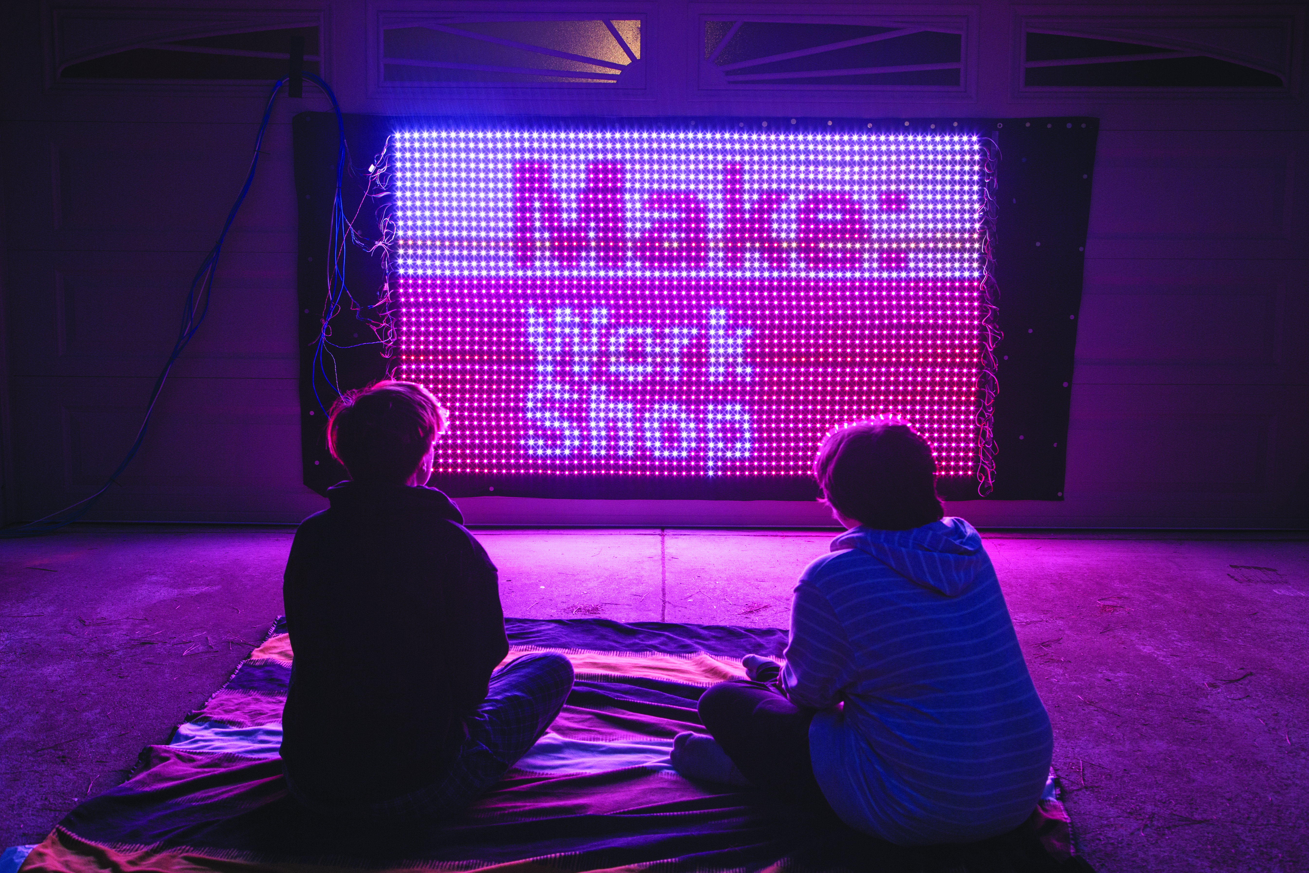
It’s a giant DIY TV! When you’re done building it, making the lights do what you want is as easy as editing a video — no coding required. Hang your LED screen on a wall, or take it to your next outdoor festival and blow people’s minds.

I’ve written open source code to upload any video from anywhere to your new LED wall. All you have to do is put it together. The Teensy microcontroller from PJRC, paired with their OctoWS2811 shield, makes controlling lots of LEDs really easy using the Arduino programming environment.

This project, when completed, measures more than 2m (6′) wide, so it is best done with a friend.

Read through these steps. Knowledge is power!

When you’re done, show us what you got! Tweet your finished wall to @marginallyc and @make, and share in the comments below!

Project Steps

Collect all the parts

I’m happy to sell you a box full of LEDs and electronics if that will simplify your life.

Connect Teensy and Octo shield

Solder the headers onto your Teensy and then attach your OctoWS2811 Adaptor. The Teensy will receive video from your PC and then transform it into the language of LEDs.

Solder power connectors to LEDS

Solder a male T-connector to each LED strip, and a female T-connector to only 18 of the strips. Arrows on the strip point to the female end; power goes in at the male end and out at the female. The strips will alternate direction in a zigzag pattern so power can pass through 2 at a time (and data 12 at a time). So be consistent about your wire colors! Switching in the middle would break the Ghostbusters Rule (don’t cross the streams).

Prepare the data cable

Strip 12″ from one end of the CAT5 cable to
expose the 4 wire pairs inside.

The female JST SM connector has 3 wires: white, green, and red. The red one’s not used here. Solder the green one to the orange CAT5 wire, and solder the white one to the orange/white CAT5 wire. Now you have a CAT5 cable that has RJ45 on one end and a SM connector on the other.

Solder female SM connectors to 2 more exposed pairs: blue and blue/white, and green and green/white. The brown and brown/white pair is not used. Double-check your work — and label both ends so you can sort them later.

Prepare the power cables

One CAT5 cable can power 8 LED strips, so you’ll need all of 4 cables and some of a fifth cable. They’re all prepared the same. Take one 9′-long CAT5 cable and expose the wire pairs at both ends. One solid colored CAT5 wire will connect to one red power wire on an LED strip. The white CAT5 wire will connect to the white power wire on the LED strip.

We soldered female T-connectors here too, so we could unplug the wires.

Sew the velcro (optional)

We sewed a velcro border on the back of the fabric, so we could easily dismantle and roll up the LED wall. You can use the velcro to mount it to a wall or a stand-alone frame.

Mount the LED strips

Lay the fabric flat on the floor. Lay the first strip at the “top” of the wall with the male end on the left (arrows pointing to the right), and stick it down using its adhesive backing (extra glue won’t hurt). Lay strip 2 below the first one, with arrows pointing left. Repeat for all 36 LED strips. We used masking tape with measured marks to make sure our strips were evenly spaced.

Connect power

Follow the power wiring diagram to connect power to every second strip. On the left side, connect every odd strip (1, 3, 5, etc.) to a power cable. On the right side, connect strip 1 to 2, then 3 to 4, etc., all the way down.

Each power cable then connects to a power
supply — solid colors to VCC, white wires to GND.

Connect data

You’ll connect the data cables in 12-strip blocks. Connect Data line 1 (orange and orange/white) to the first LED strip’s male SM connector. Then connect the next 11 strips, zigzagging, down through strip 12. Connect Data line 2 (blue and blue/ white) to strip 13’s male SM connector, zigzagging down through strip 24. Connect Data line 3 (green and green/white) to strip 25’s male SM connector, zigzagging through strip 36.

Now plug the data cable’s CAT5 connector into the Octo shield’s port 1.

Wire the power supplies

Cut the end off the three PC power cables, strip the wires, and connect them to the power supplies. Remember that black goes to (L) Live, white to (N) Neutral, and green to Earth (ground).

We found it easiest to use a power splitter so that one switch could control the whole wall.

Program the Teensy

Download the Arduino sketch for the Teensy from Github, then upload it to the board using the Arduino IDE. When the Teensy reboots and you turn on the LED wall power, it should display a test pattern. If not, check your power connections and the Octo shield connection.

Test your jumbotron!

Grab the Processing sketch from Github too, and run it on your computer. A section of your screen should appear on the LED wall. Move your video program into that part of your screen and hit Play. Turn your speakers way up. Make popcorn, turn off the lights, and enjoy.

Using Your DIY Jumbotron

Color quality — You might see some discoloration in the 12th strip. This is because the data and power lines are long. Try doubling the number of data lines, or get bigger power supplies.

Video sync — The Processing sketch on the PC sends one 3-byte RGB pixel (24 bits) to the Teensy for each RGB LED, from top left to bottom right. But occasionally these messages never arrive. Over time, this can make the video really weird.

To fix this, the PC uses color 000 as a frame marker, which tells the Teensy “I’m done sending this frame, show it and we’ll start the next one.” To ensure that color 000 never happens at the wrong time, Processing adjusts each pixel so that a 0 in any color channel becomes a 1.

Audio sync — If your computer is slow, the video on the LED wall will lag behind the sound in your movie. You can easily adjust the audio delay by using VLC media player. The Processing sketch is the bottleneck — you could also try a faster computer or try optimizing the OctoWS2811 code (learn more at the PJRC site) to run the video faster.

Break the grid — The LEDs don’t have to be a grid — they could be wrapped around a piece of art, or a car, or hung across the ceiling.

Use a diffuser — Jumbotrons are best viewed from a distance. Diffusion can blur the pixels a little so the brain has an easier time seeing the picture. Try hanging a bedsheet in front of the LEDs.

SELFIETRON — Use the camera on your laptop as the video source for the Processing sketch.

Next level — Replace the Processing sketch with your own. Build a classic video game and add a joystick?