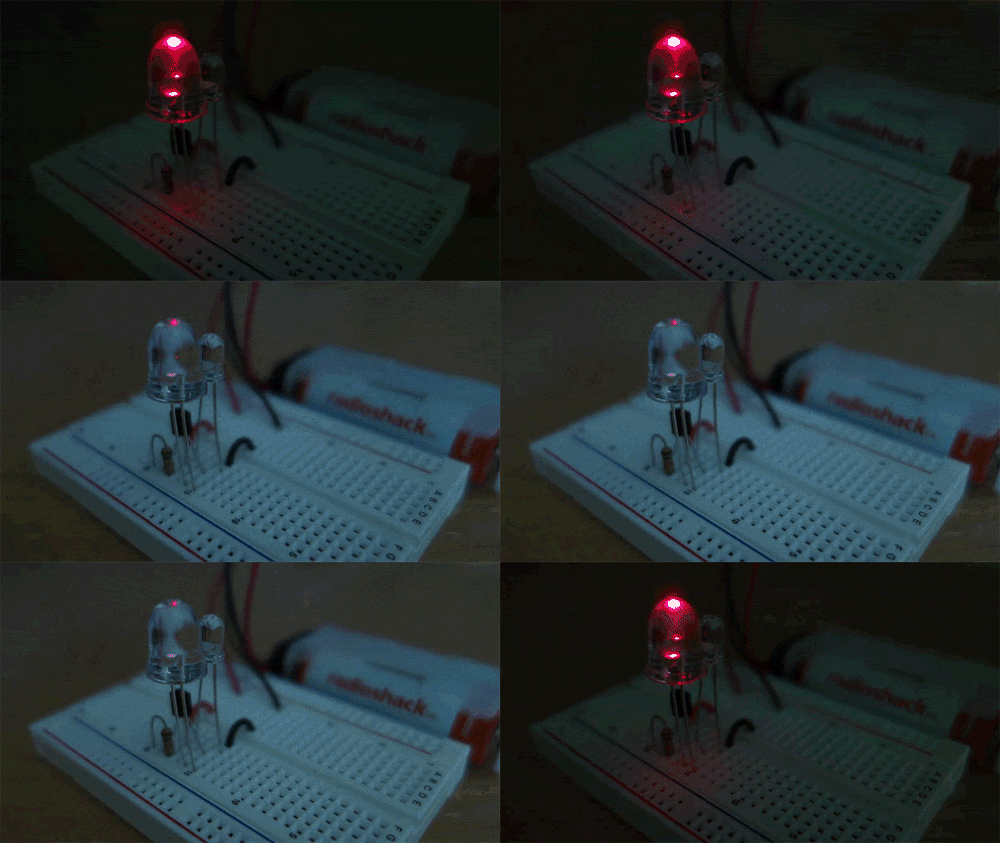
The Dark-Detecting LED is a classic beginner electronics project inspired by Windell Oskay from Evil Mad Scientist, knitted electronics, and instructables user abbtech, among other sources. I’d also like to thank John Hewes from Electronics Club for his infinitely helpful website assisting my understanding of transistors and other components. For any beginner, I should also mention the Encyclopedia of Electronic Components, Vol. 1 by Charles Platt will prove incredibly helpful in understanding the individual components of this and many other Weekend Projects.
Simply put, the Dark-Detecting LED circuit switches on an LED when ambient light levels dip below a certain threshold. I’m sure you’ve seen “garden lights” that perform this function, but none with this few components.
I recommend this project for beginners and enthusiasts alike because:
- The brilliance of this project is achieved with only five common components, including many that you might already have laying around your workbench!
- That said, it’s a fun and easy project to build with leftover components.
- You can quickly iterate the circuit on a breadboard to experiment with components, which in turn help you understand how changing any of those components effect the output of the circuit.
- If you’re looking for a challenge, try soldering the components together point-to-point (see Steps 7-9 below). Again because of the relatively few number of components this will be a challenge while requiring relatively few solder points — only seven!
Schematic

You can see the circuit contains only five components: battery, phototransistor, resistor, LED, and transistor. The parts listed for this project contain variations of all of these components. You can choose a la carte the components you want for their physical or aesthetic properties, but it really boils down to these five components.
For instance, you could choose to use a 3V coin cell battery and holder, or two AA batteries in a battery pack. You could choose a directional red LED in a clear package or a diffused one in a colored package. It all depends on where you want the project to eventually live, and how discreet or embedded you want it to be. However it should be noted that this design is only guaranteed to work with the specified components. You can’t simply replace the red LED with a blue or white one, due to the differences in forward voltage (and other specifications) required by each LED. Spend some time reading up on LEDs and Ohm’s law and you’ll be experimenting in no time!
True Story
I kid you not, while prototyping this circuit myself I encountered a resistor — a regular 1/4W 5% resistor, the kind you remove from any pack of resistors — that would only operate in one direction, as if it had polarity! Thus I recommend you first prototype on a breadboard to ensure your components operate properly. Plus doing so takes only a few minutes of time.
The Transistor

The 2N3904 is a common low-power NPN transistor used in many hobby electronics projects. Unlike most simple electronics components that have two leads (typically anode and cathode; or which operate as junctions between other components, like resistors) this transistor has three leads. 
Here’s a picture of a 2N3904 in a breadboard, with the leads indicated:
When prototyping on a breadboard, a trick I use to orient the transistor properly is to imagine the symbol overlayed over the component like so:
I align the flat side of the transistor with the bar in the symbol, and the curve of the transistor package with the symbol, keeping the arrow visible. This allows me to quickly place the leads or indicate their function. I doubt the component and symbol were designed with this in mind, but it’s a rather serendipitous visual aid nonetheless.
As shown in the schematic above, when photons (particles of light) hit the phototransistor, the transistor – and with it the LED — is effectively switched off. When a diminished number or no photons hit the phototransistor, current freely passes through the transistor’s collector-emitter junction, lighting up the LED. Experiment with the components you have available and share with us in the comments below any clever uses for this circuit you come up with!


