This project is part 1 in the building a robot arm tutorial. In the second part I show how to design the base and in the third part I show how to design the mount section. Part four will show how to add control with an Arduino.


Header

The best part about robots is that they can take any form you want them too. From little Roombas to large scale industrial manufacturing robot arms, there is almost no limit to what form a robot can take.

Still, some robots seem a little more out of reach than others. Those large-scale robots that build your cars are both extremely expensive and extremely complex. Yet thousands of people who have been able to either produce or retool them have found ways to do incredible things with them. For example, have you ever seen the movie Gravity? All the scenes where Sandra Bullock is flying through space are all shot using industrial robot arms.

My question to you is what would you do if you had access to these robot arms? What would you do if you could change them and shape them however you liked? And what would you make if you knew how to use them?

Let’s go explore that question. Let’s explore how to design, build, program, and then play with our own 3D printed robot arms. In the coming posts we will step through the process of modeling 3D parts using Computer Aided Drafting, or CAD for short. We will explore what kinds of parts we will need to build these robot arms on the cheap, and how to make sure that they are incorporated into the design.

After all the CAD work is done, we will 3D print our parts and assemble them. Later, we’ll still have to learn how to program and control the robot. After that, well, the sky’s the limit, and even though I will show you what I want to do with these robot arms, I am more excited to see what you do.

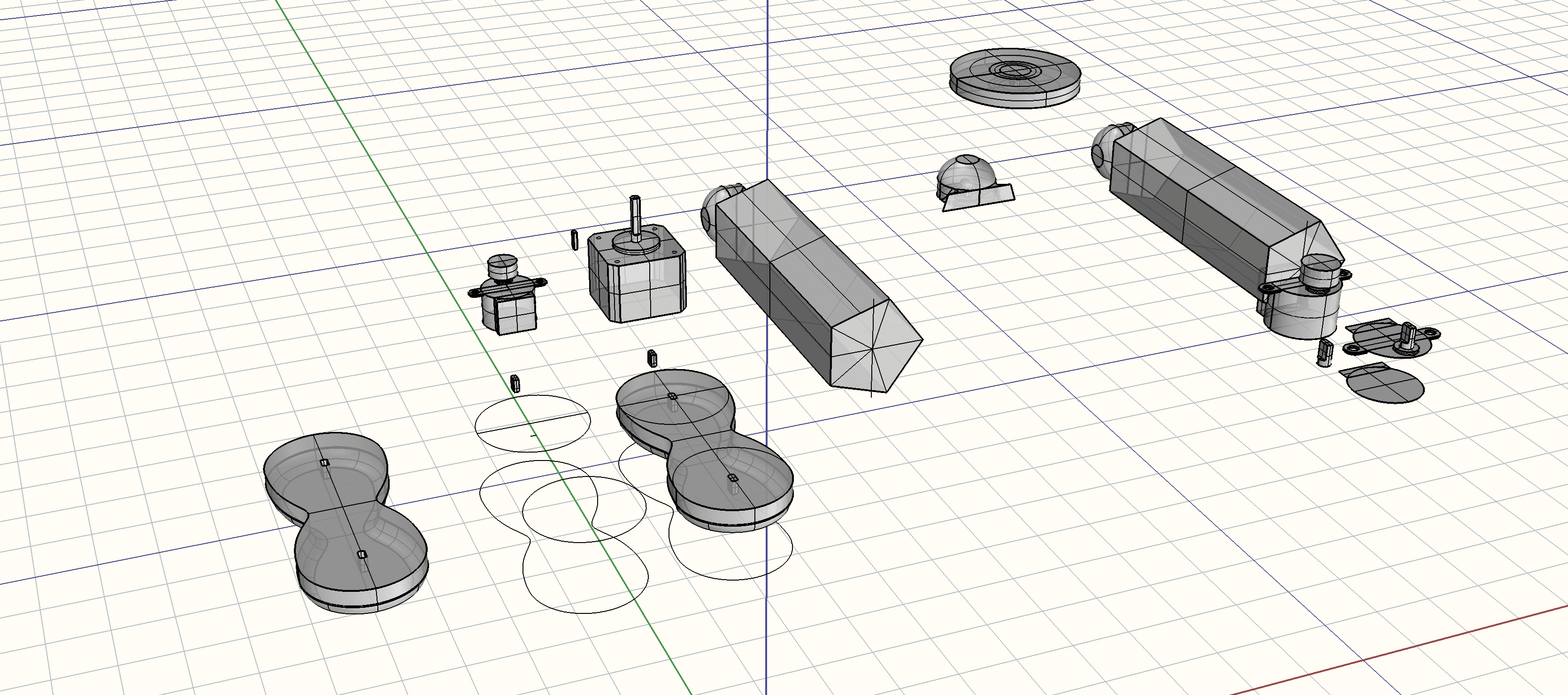
Let’s not get ahead of ourselves here though; first we have to design all the components. The very first thing we want to do in any project is get our materials.


Project Steps

Order Your Motors

Ordering small motors is important because the more weight you add to the robot arms the harder it will be to move them.

I got mine from Adafruit

Choose Your CAD

Finding the right CAD can be difficult, the learning curve is step on many and most of the best ones are not free. I use, and all my screen captures will be of, a program called Rhinoceros. It is a professional CAD tool that is used by architects, industrial designers, and some mechanical engineers.

I use it because it is fast and extremely accurate. It also currently free for beta on Mac, though it is not free for PC. If Rhino is not an option for you, or you think it is too complicated, don’t worry; there are a number of other excellent tools out there that can be used to generate 3D print files. Autodesk has a program call Fusion 360 that is free for students. There is also Sketch Up that was for a long time developed by Google. All are perfectly fine options and you should feel free to use what ever you are comfortable with.

Measure the Drive Shaft

I start by measuring the drive shaft, the long bit that spins when you power it, of the stepper motor and modeling it in the CAD software as exactly as possible. I use the calipers to measure the width and length and height of the shaft. I do this because I want to integrate my virtual model into the real dimensions of the motor.

Model the Real World Assets (Model the Motors)

Here I modeled the entire motor by measuring using the calipers. While this is not entirely necessary, I did so to use it as a scale reference and to help me visualize how I wanted to build the arm component.

Offset the Drive Shaft Head

We now make sure to offset the surface of the head of the drive shaft. We do this because as we design our arm we will want to incorporate holes in the arm that the drive shaft can fit into. Due to the way all 3D manufacturing works, you will always need to offset surfaces in this manner because the 3D printing process isn’t perfect and won’t print as accurately as we’d like.

I offset the surface by .02″.

NOTE: It is critically important you follow this step because if you do not offset for the tolerance of imperfect, then nothing will fit together.

Defining the Shape

Once you have the exact dimensions of the drive shaft then it’s time to design the arm. I drew the shape in two dimensions at first. I used two circles and connected them to create my arm shape.

Extrude the Shape

Now extrude the shape you drew by about .375″. This should create a solid form.

Fillet the Edge

Now just fillet the edge using a fillet command. You will probably have to experiment on how dramatic you want the fillet to be.

Subtract the Drive Shaft from the Arm

Finally use a boolean command. This is a fancy way of telling the software to subtract on object from another object. This will remove the drift shaft shape from the arm object.

Print!

Now put this into your favorite slicer and print!

The motors should fit right into the slots you modeled.

Conclusion

In the next post I'll go over in more depth how to design and assemble components that interface with each other. This will bring us into a more functional robot arm taking it step by step so that we can build something interesting together. If you have any questions feel free to email me or post comments, and if you want to see new things or have me explore a part of this continual project, then put it in the comments!