My new video project4

You have probably seen signs in public restrooms that remind people to wash their hands. And you have probably wondered just how often this sign gets ignored. Well today we are going to make a simple alarm that will tell you (and everyone else in the room) whenever someone forgets to wash their hands.

[youtube:http://youtu.be/yrhn47PkfOQ]

View the project on instructables: www.instructables.com/id/Unwashed-Hands-Alarm/

Project Steps

How This System Works

Here is how the system works. First a sensor detects when the toilet is used. Then a second sensor detects when the sink is used. A third sensor detects when the restroom door is opened. An Arduino microcontroller monitors all of these sensors, and if someone uses the toilet but does not use the sink, an alarm will sound when they open the door to leave. This will alert everyone in the room that they did not wash their hands.

The Arduino Code

[protected-iframe id=”ee60f217fc1662a24ef508718d15084b-30206320-62929444″ info=”https://gist.github.com/nhurstmake/677eaf0a1c0d06ff0008.js” width=”600″ height=”2600″]

The Sensors

There are several different kinds of sensors that you can use for this project. To detect when the door is opened, I chose a magnetic reed switch. To detect when the toilet and the sink are used, I chose to use a piezo sensor.

The piezo sensor mounts to the pipes of the toilet and the sink. When water moves through the pipes, the piezo element turns the vibrations into a small electrical signal. This signal is amplified by a simple OP AMP circuit and sent to the microcontroller.

Prepare the Piezo Element

Just about any piezo element can work for this project. You can find these in most electronics that beep (watches, timers, etc.). However, if your piezo element is mounted inside a plastic housing, you may need to remove it. Also you should be aware that many piezo buzzers have built in circuitry that also needs to be removed. Here is a simple example.

I purchased a small piezo buzzer from Radio Shack. First I removed the housing by prying it open with a small screw driver. Inside was the piezo element and a small driver circuit. Then I cut the wires that where connecting it to the driver circuit board, leaving the piezo element and three attached wires. You want to connect to the outer ring and large white circle (not the center tab). So I also cut the wire that was connected to the small center tab. The remaining two wires will connect to the amplifier circuit.

The Amplfier Circuit

The amplifier circuit that I chose to use for this project is a basic 741 OP AMP amplifier. I based it on a circuit that was used by Instructables user staceyk in her instructable “Low Cost Water Flow Sensor and Ambient Display.” It is powered by the 5V pin on the Arduino. The two 4.7k resistors create a voltage divider that set the base signal at 2.5V. By keeping the signal voltage at the mid-range of the supply voltage, you can monitor voltage changes in both directions.

Three of these sensors are constructed for the toilet pipe, the sink’s cold pipe and the sink’s hot pipe. The output of each amplifier circuit is sent to the analog input pins on the Arduino.

Prototype the Sensors on a Breadboard

First, I prototyped the amplifier circuits on a breadboard for testing. I started by testing the code using an array of switches in place of the piezo sensors. Once that was working, I attached the piezo sensors and the amplifier on a second breadboard.

I hot glued one of the piezo elements to the cold water pipe of my sink. Then I used alligator clip jumper wires it to connect the piezo element to the amplifier.

Try turning the water on and off. If the sensor does not detect the water, try adjusting the sensitivity in the code. If you are still having problems, you may try changing some of the resistor values to adjust the amplification. You can also try moving the sensor to a different location on the pipes.

Once your circuit is working, you can solder the amplifier circuit onto to a circuit board.

Solder the Parts onto a Circuit Board

Next you need to solder all the circuit components onto a circuit board. When attaching the power and output wires, be sure that they are long enough to be able to reach from the sensor to where the Arduino will be mounted.

Alternate Sensor Design

In some cases, these sensors will not be able to detect the water moving through the pipes. Sometimes the pipes just won’t vibrate very much when used. Other times the building will experience significant vibration from other sources and cause false triggering of the sensors. If this happens you need to use some alternate sensor to detect when the toilet and the sink are used. Here is one example.

You can use a simple pair of wires to detect the presence of water. Water conducts electricity well enough that it can be used as a low power switch. To do this, connect one wire to ground and a second wire to an input pin on the microcontroller. Then connect a high value resistor (100kohm or higher) between the input pin and the positive supply voltage. This resistor acts as a pull-up resistor and will cause the input pin to normally read HIGH. But when the ends of the two wires are submerged in water, they will connect the input pin to ground and it will read LOW. This works as long as the resistance of the water is less than the resistance of the pull-up resistor.

To sense when a toilet is used, you can mount a pair of wires inside the tank of the toilet. (Do not mount the wires inside the bowl). Mount the wires so that the ends are just below the water level in the tank. With the ends of the wires submerged the input pin will read LOW. When the toilet is flushed, the water level drops and the wires will no longer be connected through the water. This makes the signal at the input pin HIGH until the tank refills.

To sense when the sink is used, you can mount two wires underneath the faucet. Place the wires so that they will both be hit by the stream of water when it is turned on.

The Door Sensor

To sense when the door is opened I used a magnetic reed switch. These are commonly used in security systems to detect when doors and windows are opened. A magnet mounts to the door, and the reed switch mounts to the wall next to it. When the door is closed the magnet pulls the contacts on the switch together. When the door opens, it breaks the circuit.

To use this, connect one wire on the reed switch to ground and the other wire to an input pin. Then connect the input pin to the positive supply voltage with a high value resistor (100 kohm works well). When the door is closed the input pin will register a LOW signal. When the door opens the input pin will register a HIGH signal.

The Alarm

The alarm can be anything that you can dream up. I decided to use both a buzzer and lights around a sign.

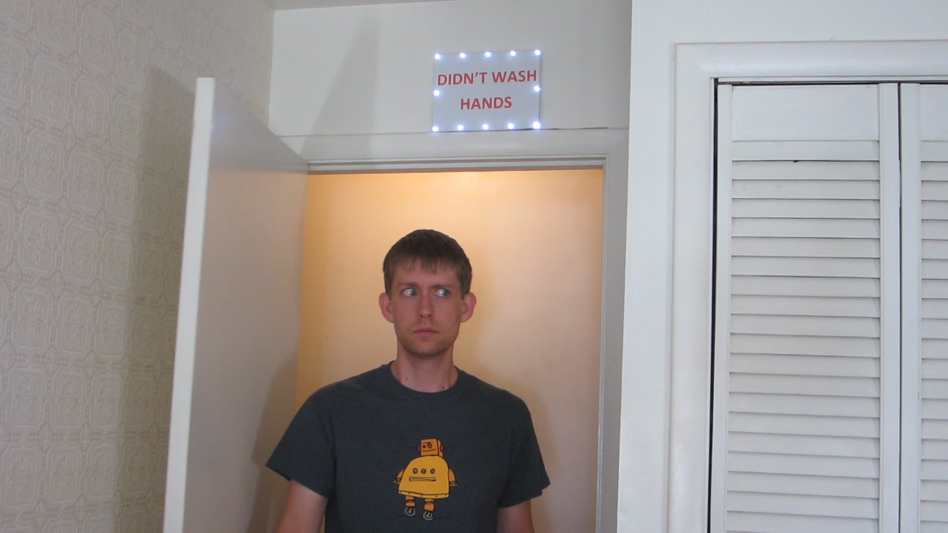
First I printed out a “Didn’t Wash Hands” label on my printer. Then I cut several pieces of cardboard so that they were a little smaller than the paper. I attached the cardboard and paper with glue and folded the paper around the sides.

Next I decided where to mount the LEDs. At each location I poked holes for the leads of the LEDs. Then I inserted the LEDs and bent the leads down so that they were flush with the back of the board.

The LEDs are powered by the same 9 volt battery that powers the microcontroller. Because the LEDs run on 3 volts, I wired them together in groups of three LEDs in series. This lets me leave off the series resistor that you would normally need for an LED.

The buzzer is connected in parallel to the LEDs. It can be mounted anywhere that is convenient. You can attach it to the back of the sign or next to the sign or wherever.

The alarm is activated by a single power transistor. The negative terminals of the battery pack is connected to the GND pin on the microcontroller. Then the output pin on the microcontroller is connected to the base of the transistor. When the microcontroller sends a HIGH signal to the transistor it turns on the lights and the buzzer.

The Finished System

Once all the parts are in place you can test it out. Flush the toilet, then open the door. The alarm should sound for five seconds. Then wait one minute for the system to reset. This time, flush the toilet and then turn on the sink. Now when you open the door, the alarm shouldn’t go off. This will be a big surprise for the first person that doesn’t wash their hands at the restaurant.

The code for this project is written for private restrooms with a single toilet and sink. But you could potentially modify it to accommodate more sensors.

As a final note, I need to give some credit to Gary Larson, who made a Far Side comic that inspired this project. If you are not already a fan of Gary Larson, I highly recommend reading his comics. There is a lot of inspiration to be found in his work.