


I got all the parts necessary for the project at my local RadioShack. You can get them cheaper somewhere else, I’m sure.
Projects from Make: Magazine
Dummy Camera
Use a 555 timer to make an LED blink like the one in a security camera.
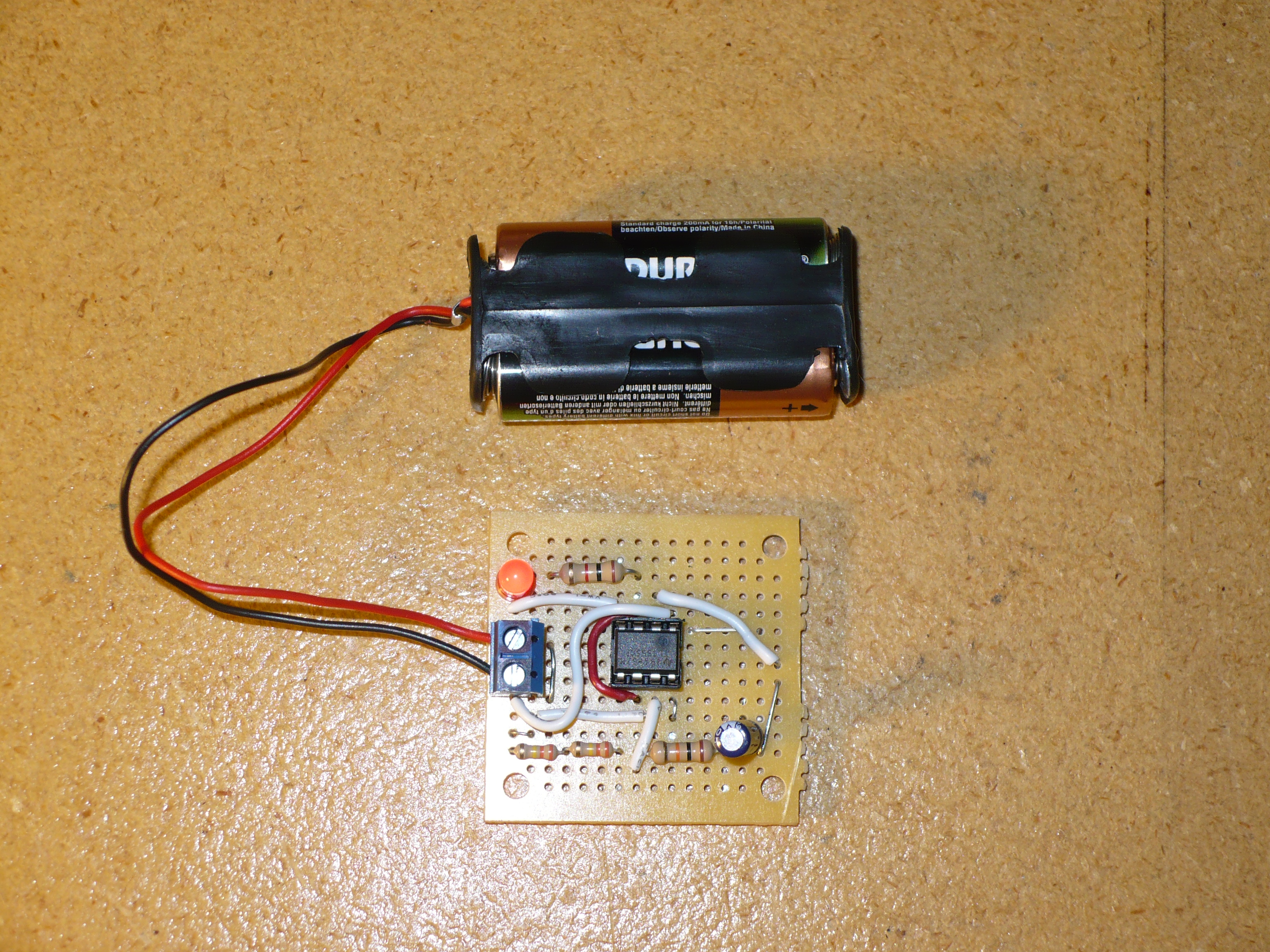
Use a 555 timer to make an LED blink like the one in a security camera.
I got all the parts necessary for the project at my local RadioShack. You can get them cheaper somewhere else, I’m sure.