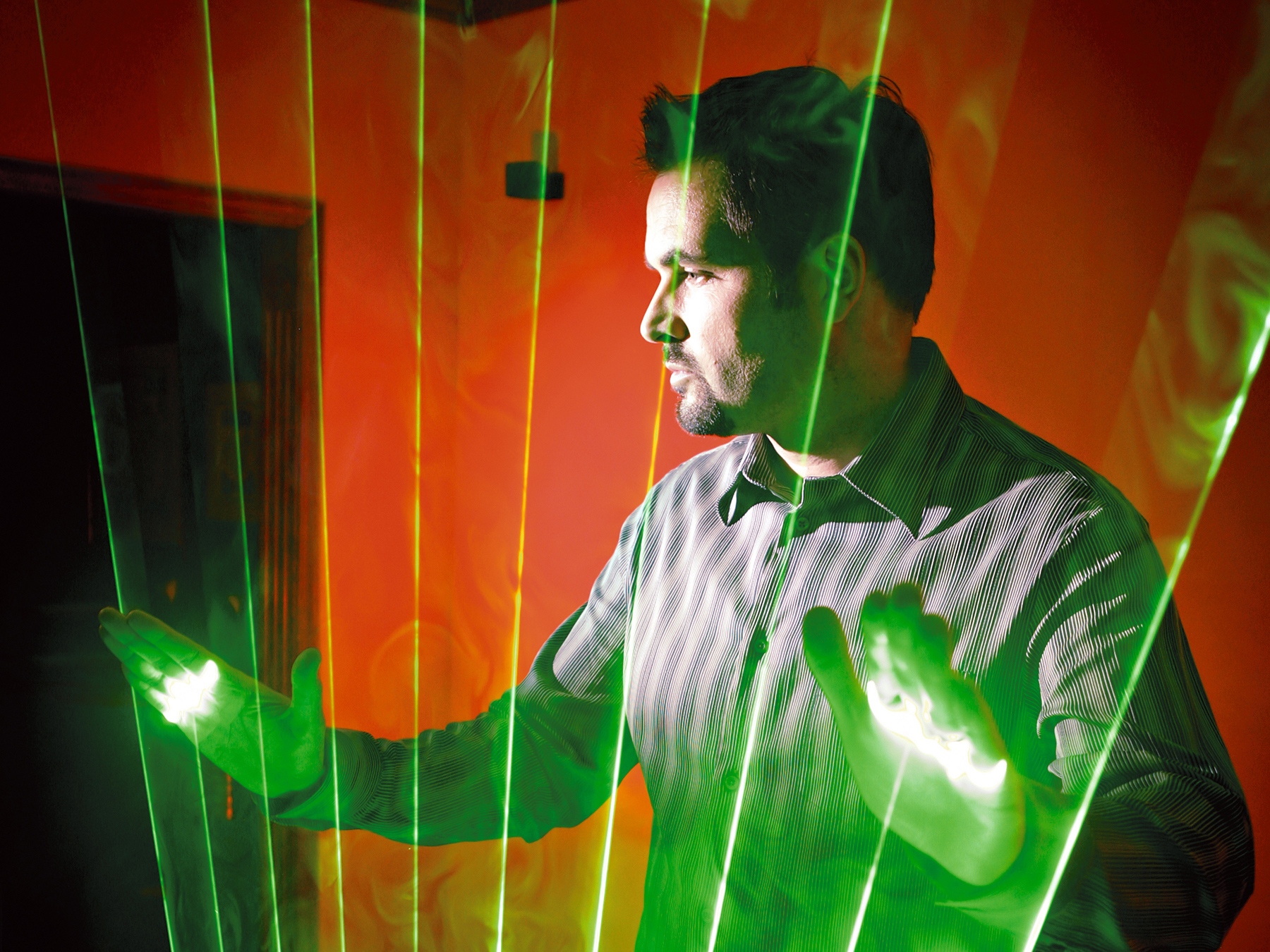
One of my most vivid concert memories is seeing Jean Michel Jarre perform in 1986 at the city of Houston’s 150th birthday celebration. He played music by breaking laser beams with his hands. The beams came out of the stage and went off into space, and for a long time I thought it was a fake — I couldn’t understand how this instrument could work without any sensors above. That started me researching and tinkering, and 22 years later, I figured it all out and built my own.

Now I have several versions of the laser harp. The one I perform with uses a powerful laser and a scanning mirror system, designed for professional lighting effects, that splits one beam into multiple beams that can fan out and move dramatically. This article describes a simpler harp I designed more recently, which uses inexpensive laser pointers and doesn’t need the scanner.

The harp works as a MIDI controller, so it doesn’t make sound itself, but generates a stream of MIDI data to drive an audio synthesizer. Each beam strikes a photocell, and when the player’s hand interrupts it, the sensor prompts an Arduino microcontroller to send a MIDI “Note On” message. Additionally, a range sensor reads the position of the hand, which spawns MIDI controller messages that change the sound’s qualities.

First I’ll show how to make a single-beam laser theremin, which changes pitch with the position of your hand. Then we’ll replicate the circuit and reprogram the Arduino to produce a multi-string laser harp, with each beam corresponding to a different note. The Arduino has 6 analog inputs, so this harp is limited to 6 beams, but at the end of the article I’ll suggest ways to expand it.

Resources

Project Steps

Build the Pieces

We’ll build the main electronic components first and then put them together. We’ll start with the common power supply, light detector circuit board, and MIDI output jack. Then we’ll add photocells, range sensors, and lasers — 1 of each for the theremin, and 6 of each for the harp.

Power Supply

I built the power supply on a mini circuit board following the schematic.

A 7805 regulator steps down the 8.5V from my camcorder charger to 5V for the range sensors. An adjustable voltage regulator lets you tune the power to the lasers to just above the detection threshold.

The Arduino gets 8.5V directly, since it has its own onboard voltage regulator. To suck up any power spikes, I added a 0.1μF “bypass cap” across each of the 3 output voltages: 5V, variable, and 8.5V. These capacitors are optional.

Finally, to neaten the connections out, I used two 8-pin headers for the outputs to the lasers and range sensors.

Detector Circuits

The photocells (aka light-dependent resistors or LDRs) are on their own little boards, across from the lasers. But I assembled the rest of the detector circuitry onto the larger circuit board.

The board needs to have 1 circuit for the theremin, or 6 circuits in parallel for the harp. Each of the two LM324 op-amp chips supports 4 detector circuits, and I went ahead and created 8 circuits, even though the harp only needs 6. The 68K and 100K resistors create a shared reference voltage, so we only need 1 of each. See the schematic online.

MIDI Jack

Wire the MIDI output jack by connecting pin 5 to the TX pin on the Arduino, pin 2 to circuit ground, and pin 4 through a 220Ω resistor to +5V. (MIDI jack pins are numbered 3, 5, 2, 4, 1, from left to right, facing the pins.)

The outermost pins, 1 and 3, are not used for MIDI.

Lasers and Photocells

The lasers connect in parallel to the variable voltage on one side and to ground on the other. I soldered the photocells to small pieces of perf board for easier mounting.

They connect in parallel to +5V on one side and to the + input pins of the op-amps on the other.

Range Sensors

Anyone who has played with a touchless D-Beam control on a Roland synthesizer will recognize these sensors immediately. The GP2D12/GP2D120 range sensors fire a pulse of IR light and measure distance by triangulating on the reflection.

For musical applications, I’ve found that the output from these sensors can be noisy, due to the constantly flashing IR drawing a lot of current every 40ms. You can smooth the output by connecting a capacitor between voltage (pin 3) and ground (pin 2); I used some 300μF tantalum caps.

You can also filter the signal with a dedicated filter circuit (see schematic), or in the software, by averaging consecutive readings and using the average value.

Before connecting the range sensors, I removed them from their plastic housings. They connect in parallel to +5V power, ground, and the Arduino’s analog input pins 0–5.

The output from the range sensors is nonlinear, so the software converts output voltage into centimeters of distance using a simple equation, courtesy of Acroname Robotics.

For the GP2D12 sensor:
Range [cm] = (6787 / (Voltage – 3)) – 4

And for the GP2D120:
R = (2914 / (V + 5)) – 1

Laser Theremin

Here’s an optical version of a theremin, with 1 laser beam controlling both Note On/Off and pitch.

Download the Arduino programming software from http://www.arduino.cc. Upload the program MAKE_MIDI_ TEST.pde to your Arduino. (Included in this zip file.) This program lets the Arduino generate test MIDI messages. Set the baud rate of the Arduino to 31250.

Connect the MIDI jack to your computer with a USB-MIDI interface. Launch MIDI-OX (or equivalent software) and open that port. You should see Note On and Note Off messages in the MIDI inspector. If not, then test the +5V, ground, and TX pins for connectivity.

If the MIDI test is OK, upload the laser theremin program MAKE_THEREMIN.pde to the Arduino (also included in the zip file above).

Take one of your laser pointers apart and measure the battery voltage. Adjust the variable regulator on your power supply board until its output matches this voltage. This lets you run the laser from your power supply board. One neat way to connect it is with alligator clips.

Now make the physical frame. I cut a long piece of scrap wood into 3 pieces: to make a base, a laser holder, and a detector holder. Drill the laser holder piece for the laser to fit through horizontally, and drill a smaller perpendicular hole for a screw to hold down its power button.

Drill a hole through the detector holder where the laser will shine, tape the photosensor board to the outside with the sensor facing in, and glue a translucent tumbled rock over the hole in front. The rock diffuses the light, which helps the sensor see it.

Next, attach the range sensor to the laser. I found that it worked better mounted vertically than when it was horizontal. I think the IR beam was reflecting off the laser pointer’s barrel and causing misreadings. Having a rangefinder too close to a wall can also diminish accuracy.

Connect the photosensor circuit’s output from the op-amp to pin 2 on the Arduino and connect the rangefinder’s output to Analog In 0. Connect your computer back to the MIDI out and run MIDI-OX. Switch everything on.

Adjust the pot on the detector board so that the LED just comes on. At this point, breaking the laser beam with your hand should switch it off, and MIDI-OX should show you Note On, Note Off, and Pitch Bend messages as you move your hand in the beam.

That’s it. Swap MIDI-OX for a soft-synth, or plug the MIDI jack into a hardware synthesizer, and you’re playing!

Laser Harp

Now we’ll expand on the theremin idea and create a 6-beam laser harp.

Build the frame. I made a wooden base to hold the lasers, rangefinders, and circuitry. Two metal tubes at either end support a top tube, which has 6 holes drilled through its underside to expose the photosensors. Space the lasers at least 4″ apart, or else cross-talk between the range sensors can throw off their readings.

Wire the other lasers and photosensor/detector/ rangefinder loops in parallel with the first ones; see the schematic online. For neatness on the detector board, I used 8-pin headers for the photosensor and Arduino connections. Also check that the variable regulator can handle the current drawn by the lasers: multiply the lasers’ amperage by 6, and confirm that it’s below the voltage regulator’s rated max current. To make sure, you can also measure the current that comes into the regulator.

Instead of messing with alligator clips, I made connector plugs for the laser pointers. I cut a slot in the back of each with a Dremel tool, made a wood plug to fit into the barrel, and thumbtacked a wire to each end. Insert the plug, pass the wires through the slot, and screw on the back. The case contact in back will be ground. To keep the lasers switched on if the screws slip, wrap the barrels with electrical tape.

Connect the detector outputs from the op-amps to Arduino pins 2–7 and connect the range sensor outputs to the Arduino’s analog input pins 0–5. Adjust the potentiometer until all 6 LEDs come on. You should now be able to turn them off individually by breaking the 6 beams. If ambient light becomes a problem, cut rings of narrow PVC pipe, paint them black, and attach one around each detector. If the lasers just miss the photosensor holes, glue on tumbled rocks as diffusers.

Upload the program MAKE_HARP1_CTRL.PDE to the Arduino, and start playing (program available in zip file). The software assigns the MIDI note numbers 60, 62, 64, 65, 67, and 69 to the beams, but you can change this by editing the notearray[] structure. The controller messages from the range sensors are sent as note 74.

With my synthesizer, this changes the filter sweep and creates a funky, retro synth sound.

You can also try MAKE_HARP1_VEL.PDE, a modified version of the code that maps your hand position to MIDI velocity, to mimic how hard you would strike a key on a keyboard (program available in zip file).

You’re not limited to just playing notes. Ableton Live software allows you to MIDI-trigger drum loops, sequences, and other musical events. It’s not free, but you can download a demo version at ableton.com.

If you want to go crazy and add more beams, you’ll need to expand the digital and analog inputs of the Arduino using a multiplexer. There are a couple of neat, off-the-shelf ways to do this. I’ll mention two here, and you can find more at the Arduino Playground.

One approach is to use an analog multiplexer like the R4 AIN MIDIbox module, which is based on the 4051 chip (kit available from AVI Showtech, avishowtech.com). This will support 32 inputs, for 32 harp strings.

With some clever programming, you should be able to bypass the detector board and read the laser harp through the analog multiplexer. To do this, connect the photocell array’s outputs to the multiplexer’s inputs, feed the multiplexed output to the Arduino, and detect which beams are broken in your software.

You can also use a digital multiplexer like the R5 DIN Module, another MIDIbox kit from AVI Show- tech, which is based on the 74HC165 chip. With these, you can chain modules together to support an unlimited number of inputs.

If you want to tackle a full-sized scanning laser harp, visit my website, stephenhobley.com.

Conclusion

This project first appeared in MAKE Volume 15, page 64.