45mjC2wwV5WCnHjV

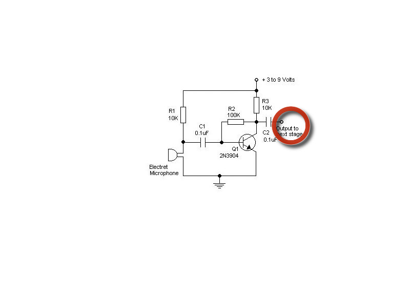
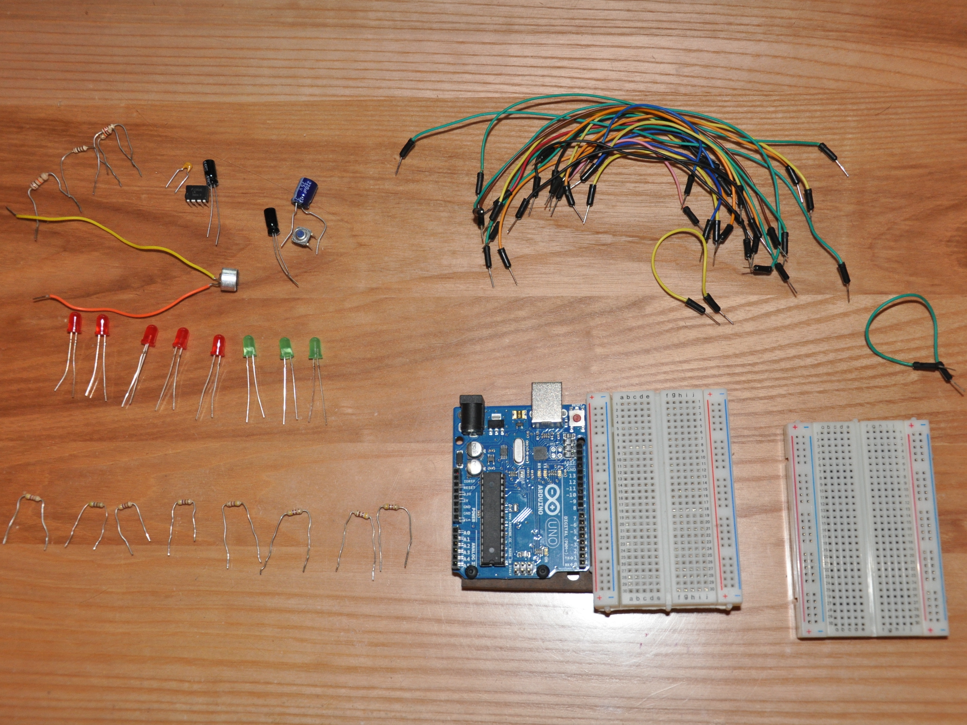
In this guide you will learn to created an array of LEDs that visually represent the volume picked up by an electret microphone. You will learn how to wire 3 different circuits which are the LED array (which is really many individual circuits), the microphone, and a button which can be used to change the display mode of the LEDs.

This guide will not cover all of the coding involved in making this, but it WILL give you the full code needed to make this work. The code is thoroughly commented and will teach you a lot if you are interested in the programming behind this.

Project Steps

Overview

This project will use an electret microphone to light up an array of LEDs as seen in the picture to the left.

Creating the LED circuit.

Connect all of your 470 ohm resistors to consecutive digital pins on your arduino, and connect the other ends to different rows on your breadboard.

Next attach the long(positive) end of your LEDS to the same row as each resistor. Attach the other end of the LEDS to the same rows on the other side of the board.

Finally connect the ground pin from your arduino to the negative column on your breadboard. Then connect all your LEDS to that negative column.

See the circuit diagram above

Creating the microphone circuit.

1. First set up the 5v and ground on your breadboard by hooking up 5v to one of the red + columns and ground to one of the blue – columns.

2. Next connect your microphone and connect the negative end to ground.

3. Connect the positive end of your microphone to a 0.1 uF capacitor. We will call this capacitor 1.

4. Next attach a transistor, with the base (middle) pin attached to the other end of the capacitor from step 3.

5. Attach a wire from the collector(right) pin of the transistor to another 0.1 uF capacitor. We’ll call this capacitor 2. Then connect the other end of that capacitor to analog pin 0. You can technically use any analog pin you want but you will have to change the number in your code.

6. Now attach the emitter (left) pin of the transistor to ground.

7. Now take two 10k resistors and attach one end to 5v. Attach one of the resistors to the positive side of the microphone. Attach the other one to the emitter (right) pin of the transistor. You are now done with the microphone circuit. Keep in mind that all the red circles in the pictures represent what you need to attach to analog pin 0.

Setting up the button.

First place the button across the middle of the breadboard.

Attach one of the pins of the button to ground.

Next attach the pin on the same side of the button, but opposite side of the breadboard to digital pin 13. In can be to any digital pin you aren’t using but you will have to change that in the code.

Finally attach the pin on the same side of the breadboard as the resistor to 5v and you are done setting up the button.

The button will be used to change display modes.

The Code

Copy and paste the code from here.

https://docs.google.com/document/d/1aj4WOO4V_QEBj0bypnzl2-VcNrHkG5lbpBcmmdRHG0U/edit

There are several adjustments you may need to make if you didn’t use the same digital and analog pins I used.

At the top you will see this. int led[] = {2,3,4,5,6,7,8,9,10}; You need to change those to whatever digital pins you used for your leds. It has to be in ascending order because the program uses for loops to cycle through the array so it would light up your leds in a random order if they are not inputted in an ascending order.

Once again same thing for the button. At the top it says int button = 13; Change the 13 to whatever digital pin you used.

Last thing is int microphonepin = 0; Once again change that to whatever analog pin you used. Remember that this one has to be an analog pin otherwise it won’t work.

Congratulations, you have made a led sound meter!

Keep in mind this is using a VERY sloppy method for getting a volume from the microphone. This leads to it being very “flashy”, as in it flashes a lot really fast, but DOES work.

If you want this to function better you could use the code I already wrote but didn’t have time to implement, which takes a moving average of the microphone values to account for the input being a wave. It also gives you the highest value during the window of that average that it takes.

You would find this code in the main loop of the program.

Enjoy your led sound meter!