Build a linear actuator from a glue stick, a servo, and a slide potentiometer.
MF_RobotLogo
Watch for our robot themed posts during May in honor of MAKE Volume 45: Robots and don’t forget to subscribe to MAKE magazine.

A linear actuator is a mechanism that pulls or pushes a load along a straight line. Pneumatic and hydraulic pistons are examples. So are the threaded rods on 3D printers.

Commercially available linear actuators can be quite expensive, but now you can build your own with just a few dollars worth of parts. Gareth from Let’s Make Robots explains the idea in this post.

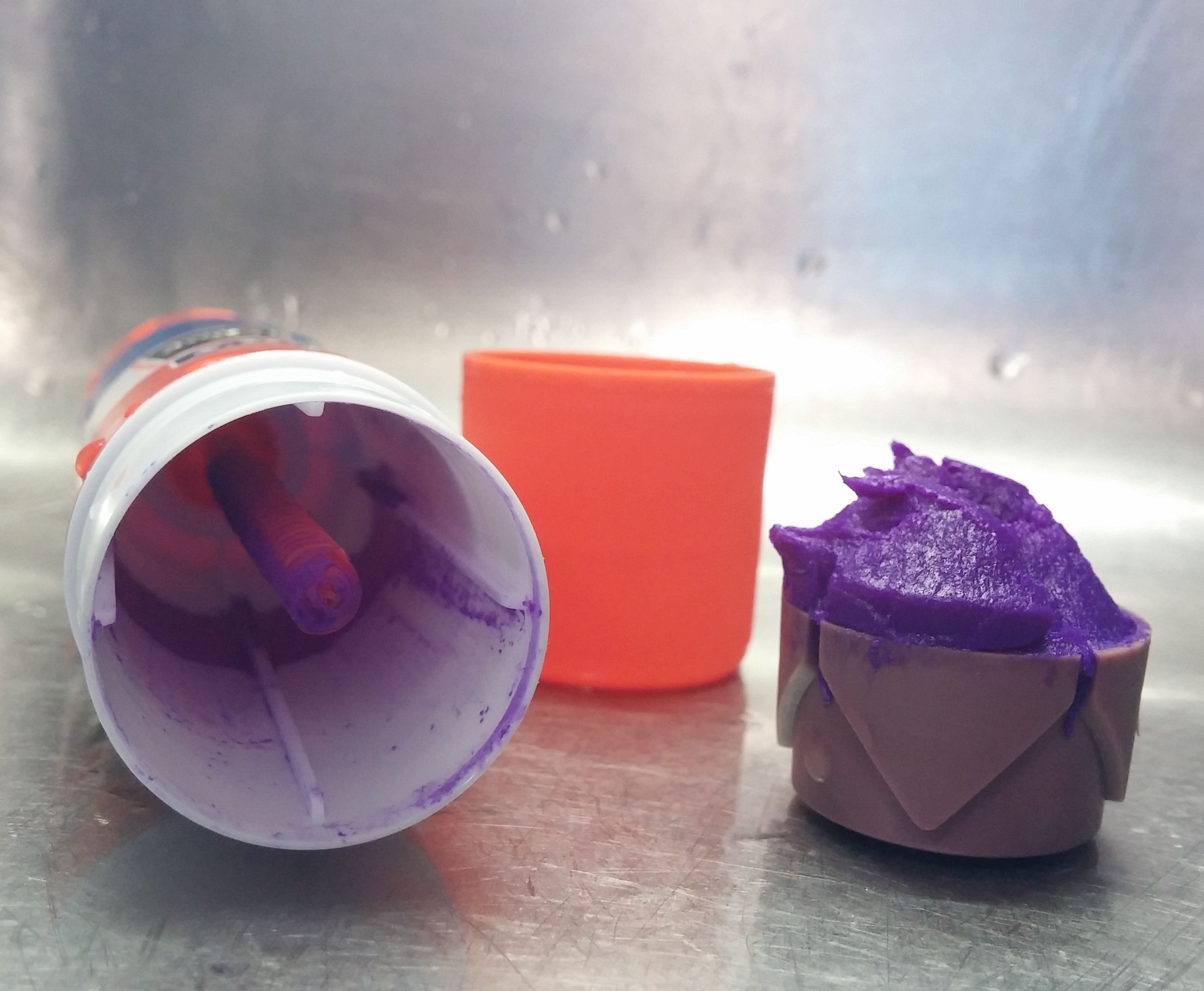
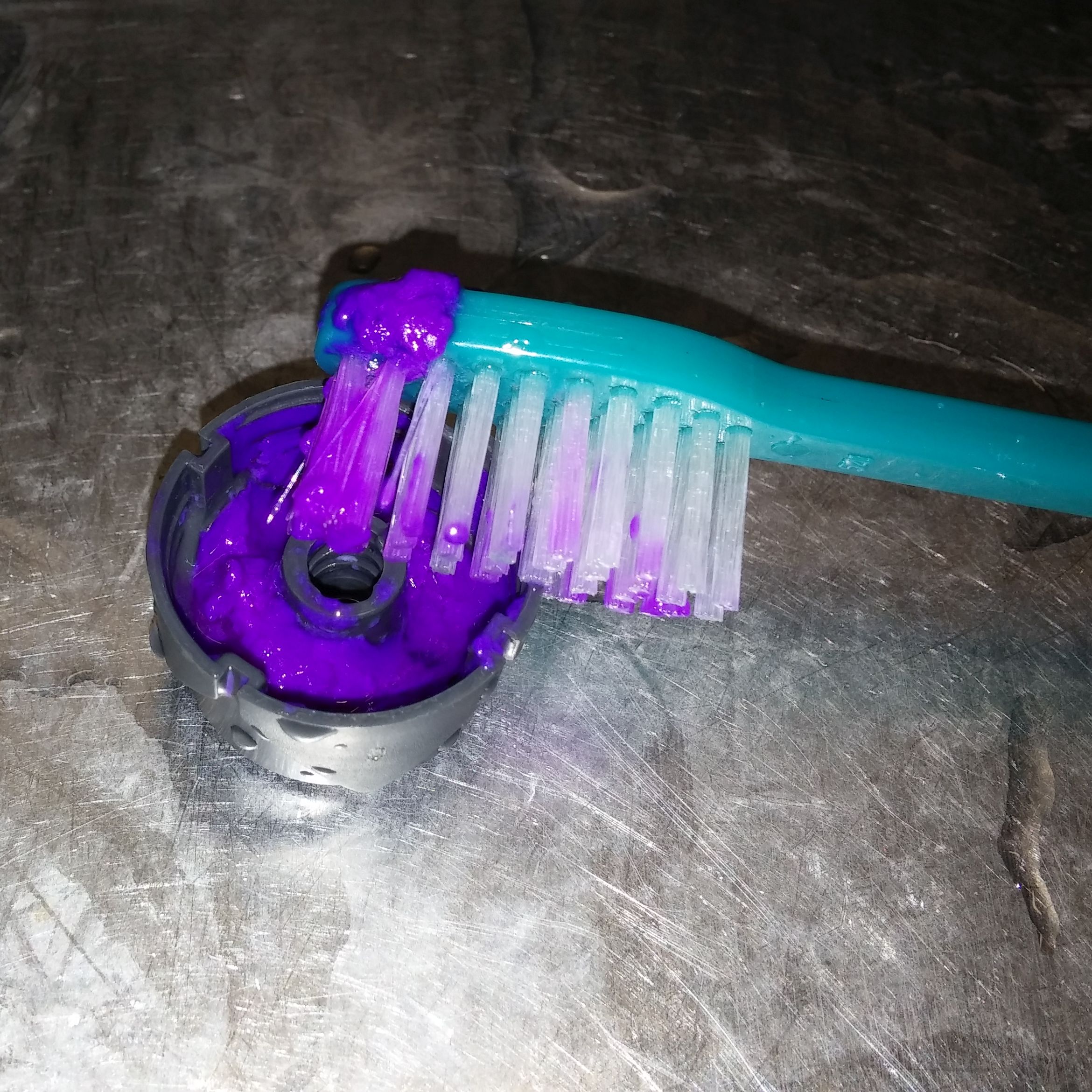
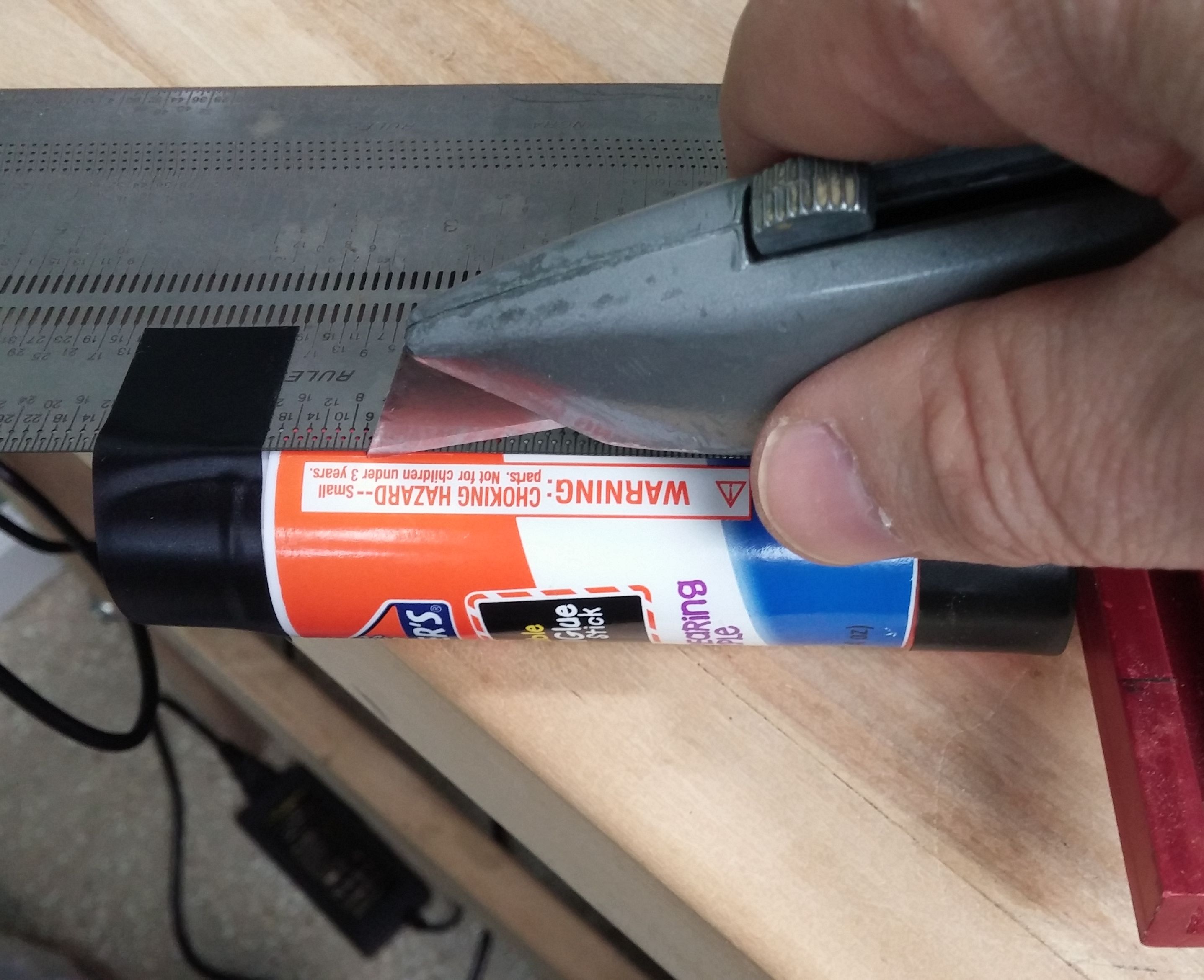
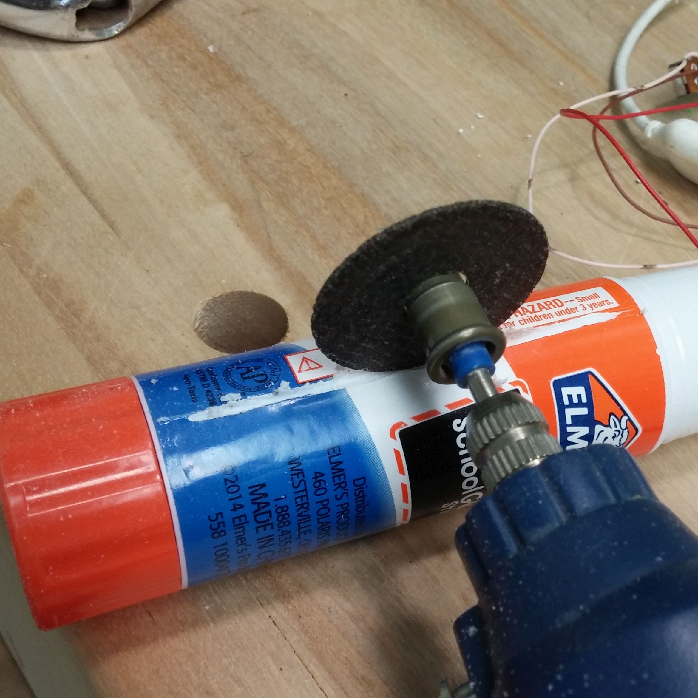
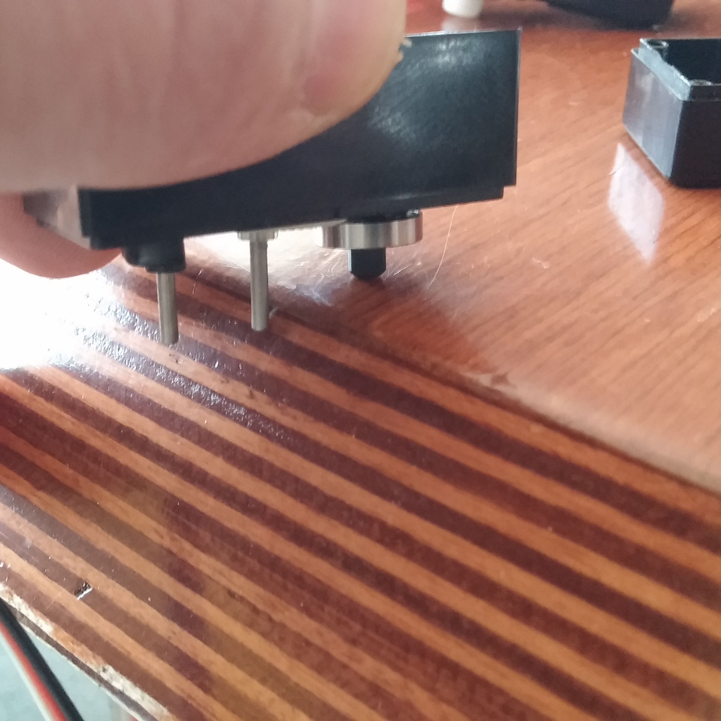
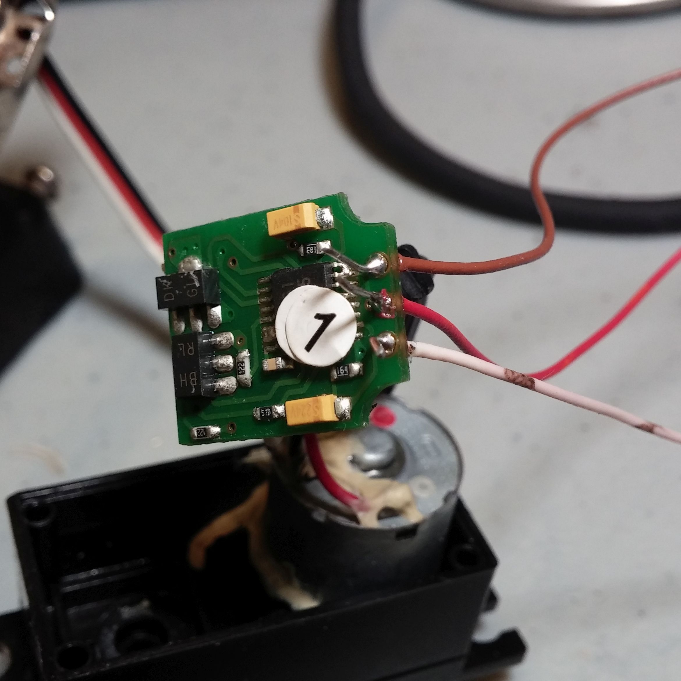
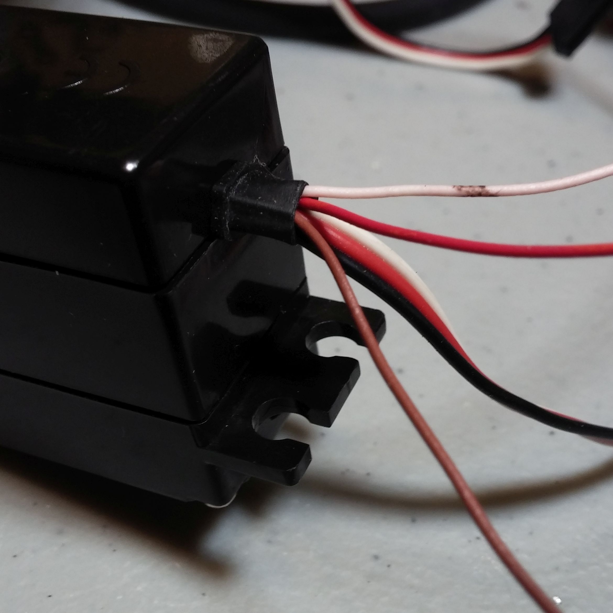
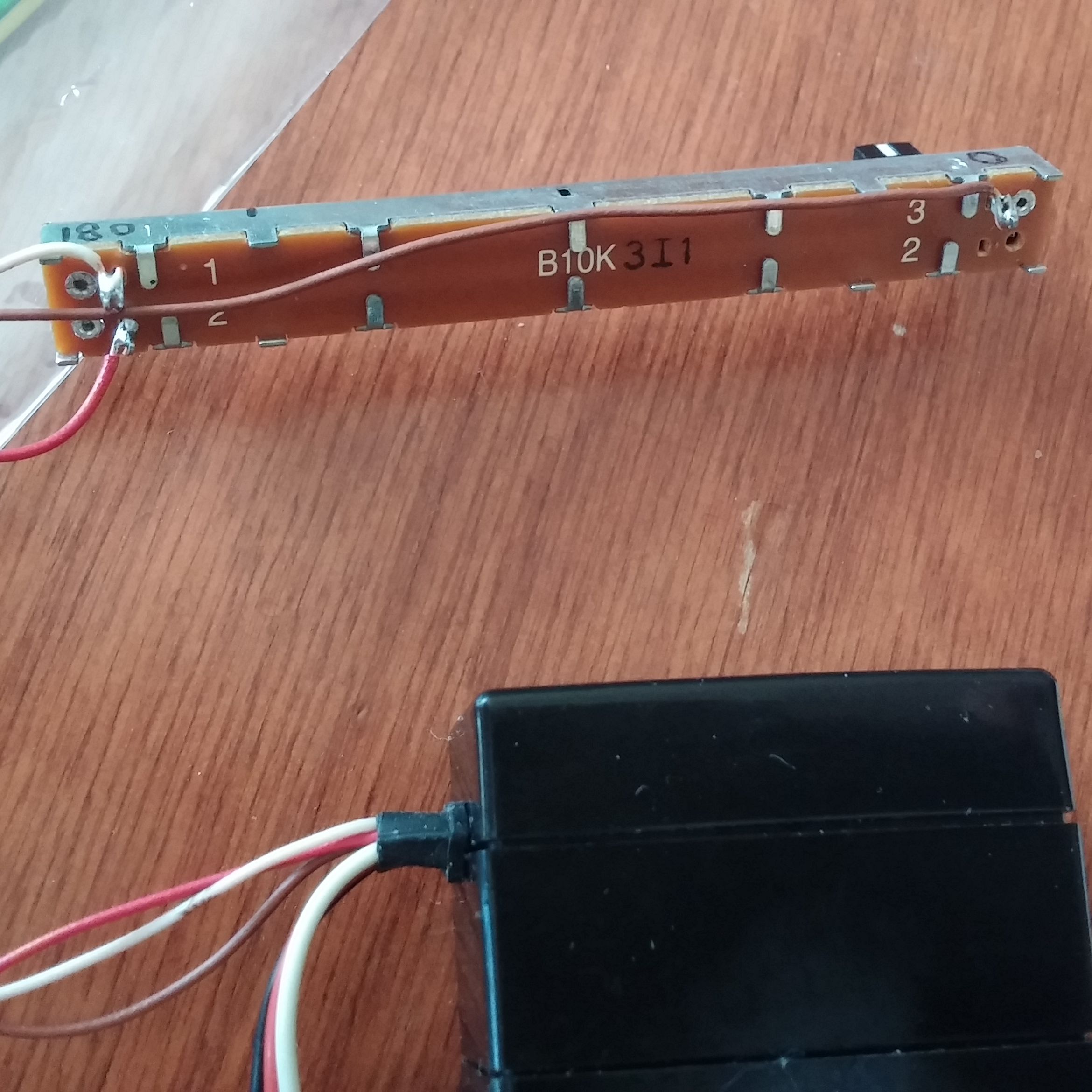
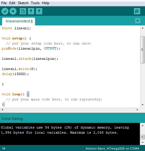
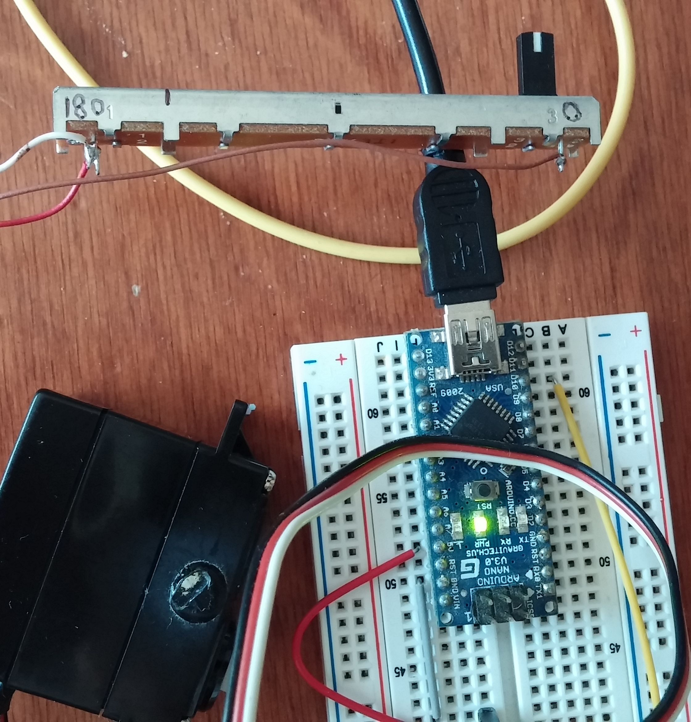
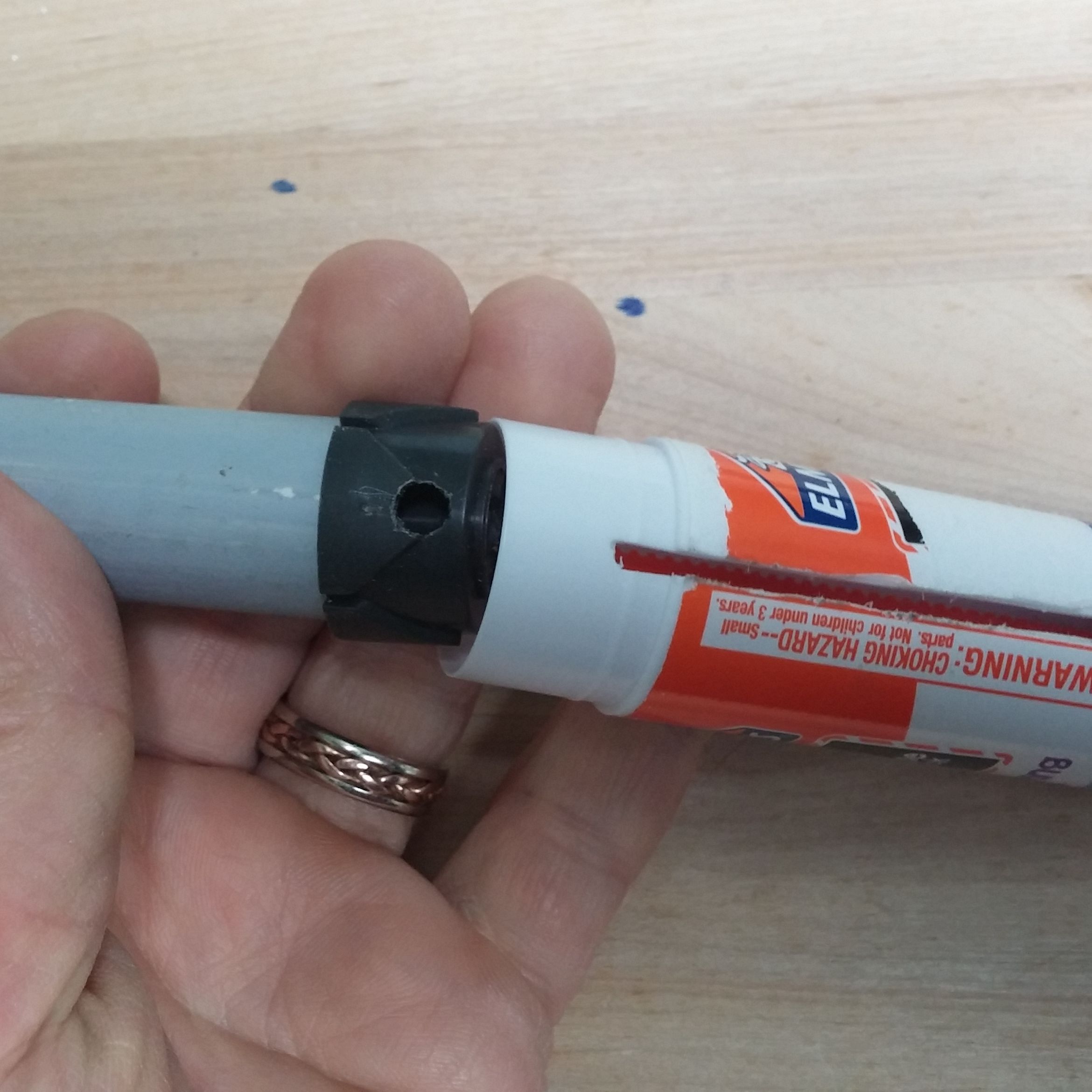
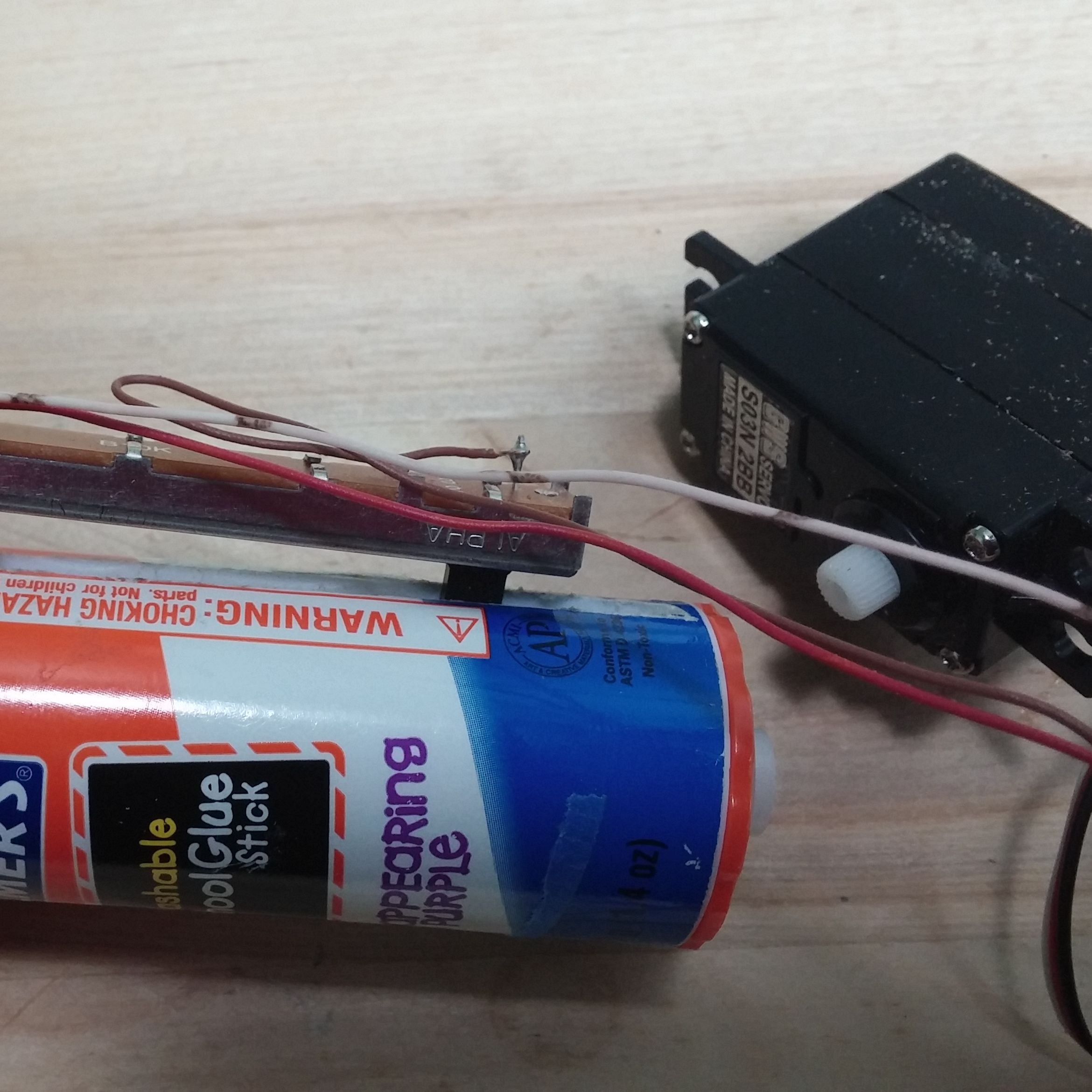
The main mechanism is salvaged from a used glue stick. By using a modified hobby servo to drive it, this actuator even comes with positional feedback. It is both surprisingly accurate and surprisingly strong. Check the video to see the finished actuator lifting a 6 lb weight!

YouTube player

The mechanical advantage of the screw drive in the glue stick lets this servo lift much more than it could normally. Try this build out, and then see if you can integrate a linear actuator into your next robot!

Project Steps

Clean the Glue Stick

Use a large glue stick, approximately 4 1/4 in. high, not including the cap.

Disassemble and remove any left over glue.

Thoroughly clean the insides of the glue stick and the moving part. Hot water and an old toothbrush work well for this.

Cut a Slot in the Glue Stick

Use the straight edge of a square to mark a line along the body of the glue stick with a utility knife.

Use your favorite rotary cutting tool to cut a slot along the length of the glue stick. The cut must be wide enough for the slider of the potentiometer to run without interference, and long enough to allow the potentiometer’s slider to travel its full length.

My initial cut wasn’t long enough, so I had to cut a little more.

Drill a Hole in the Moving Part

Run the moving part all the way to the bottom of the glue stick and center punch near the bottom, through the slot.

Drill a hole in the moving part just large enough to fit the potentiometer’s slider snugly, For my potentiometer, it was a 13/64 in. hole. Yours may be different.
NOTE: Be careful not to drill all the way through and damage the insides of the moving part!

Test fit the potentiometer’s slider in the hole.

Prepare the End of the Glue Stick

Remove the sides of the glue stick knob with a rotary cutting tool, leaving just the base of the knob. Clean up any rough edges with a utility knife.

Mix the 2-part epoxy and apply to the base of the glue stick knob.

Carefully center the round servo horn on the base of the glue stick knob. Allow to epoxy to cure for 24 hours or as directed on the epoxy instructions.

Modify the Servo (Part 1)

We need to modify the servo to allow it to turn 360 degrees freely, and to run wires from its control board to our sliding potentiometer. This step will be the same as you would do for modifying a servo for 360 rotation. These instructions and pictures will work for this specific servo, but you can find directions online for other models and follow those. Just remember we are not doing the usual 360 rotation mod.
Remove the four screws and open the top of the servo where the gears are.

Use a cutting tool to remove the physical stop from the main output gear. Remove the little white plastic bit that sits on the servo shaft above the bearing too.

Then remove the base of the servo to uncover the electronics.

Modify the Servo (Part 2)

Flip the servo over and gently press the top of the output shaft against a solid surface, like a table. This should push the electronics board out of the servo body.

Desolder the three servo potentiometer leads and remove the potentiometer. You can save it for another project.
Solder three different color 24 AWG solid wires where the potentiometer leads were. Be sure to keep track of which color is the center wire.

If you can, run the 3 wires out through the strain relief that the original servo wires pass through. If they won’t fit, you may have to cut a hole in the side of the servo.
Reassemble the servo carefully and put the four screws back in.

Connect the Slide Potentiometer

Solder the three wires you connected to the servo to the slide potentiometer leads. Make sure the center wire from the servo board (red in the picture) connects to the center sweep lead of the slide potentiometer (pin 2 on the potentiometer in the picture). Connect the other wires to pins 1 and 3 of the potentiometer.

We need to figure out which end of the slide potentiometer is which. So connect the servo to an Arduino or other microprocessor. The sample code in the second picture above will set the servo to position 0. Upload the code to your Arduino, and move the slide on the potentiometer until you find which side stops the servo from moving. (It may still move a tiny amount, but should be easy to stop with your fingers.)

Mark the side of the potentiometer where the servo stops as “0”; mark the other side as “180”.

Attach the Piston

Cut a piece of 1/2 in PVC pipe to approximately 4 in (the pipe in the picture is painted grey from a previous project, but it is normal Schedule 40 PVC).
Remove the moving part of the glue stick and press fit the PVC pipe into it, making sure you do not block the hole that you drilled for the potentiometer slide. Later if you want you can epoxy the pipe to the moving part, but a simple press fit will work for you piston if you only need to push or lift.

Run the moving part all the way down to the bottom of the glue stick by turning the knob. Then turn the knob the other way one full rotation to give some space.
Slide the slider of the potentiometer all the way down to the side you marked with a “0”. Carefully insert the slide of the potentometer into the hole drilled in the moving part through the slot cut in the glue stick.

Lay the potentiometer flat along the length of the glue stick, and secure it in place with tape. You can secure it more permanently later if you like, but just use tape for now until you’ve tested it.

Test your Linear Actuator

Attach the servo to the servo horn at the base of the glue stick, and you are ready to test your new linear actuator!
You will need to secure the body of the servo and the body of the glue stick so they don’t spin relative to each other.

This Arduino code will move the linear servo between positions 0, 90, and 180. I marked the piston at those three stops.

The linear actuator is pretty strong. It was able to lift this 6 lb exercise ball! My hand is only there to keep things balanced.
If you want to be able to pull instead of just push, you can use epoxy to connect the piston to the moving part of the glue stick. Drill a hole in the end of the piston, and you can attach a load,