The Beetlebot is a very simple little robot that avoids obstacles on the floor without using any silicon chip — not even an op-amp, and certainly nothing programmable. Two motors propel the bugbot forward, and when one of its feelers hits an obstacle, the bot reverses its opposite motor to rotate around and avoid it. The project uses only 2 switches, 2 motors, and 1 battery holder, and it costs less than $10 in materials (or free, with some scrounging).

Project Steps

Cut pieces of heat-shrink tubing and use a heat gun or other high-heat source to shrink them onto the motor shafts.

Trim the tubing evenly, with a little bit running past the ends of the shafts. These will act as tires, improving traction.

Glue the SPDT switches to the back of the battery holder, at the end with the wires. The switches should angle out at the 2 corners with their levers angled in toward each other, as shown in the image. Also, the contacts farthest from the buttons on each (the normally closed contacts) should touch. This will be the front end of our bettlebot.

Cut the metal strip, mark enough length at each end to hold a motor, and bend each end in at about a 45° angle. This is your motor plate.

Examine or test your motors to determine their polarity.

Tape the motors onto opposite ends of the motor plate so that their shafts point down and angle out.

Orient their positive and negative contacts so that they’ll spin in opposite directions.

Use cyanoacrylate glue or epoxy to glue the motor plate down onto the back of the battery holder, just behind the switches.

Orient the motors so that the left motor spins counterclockwise as you view it from below, and the right one spins clockwise. For aesthetics, I then covered the plate with black electrical tape.

Unbend a paper clip, slip it through the bead, and bend it symmetrically on either side to make a caster.

Attach each end of the clip to the corners of the battery holder at the back. I used hot glue — not very professional. You could also try bending the clip ends under and soldering them to the battery connection tabs, but if you apply too much heat to the tabs, you might melt the plastic and ruin your battery holder. Beware!

Solder together the 2 switches’ NC terminals, which are close or touching.

Then solder together their NO terminals, the middle legs. I use pieces of paper clip for short joins like this, since it’s faster and stronger.

Then connect the common leg of each switch to the front terminal of its nearest motor.

Solder a wire between the 2 motors’ rear terminals.

Connect another wire from either one to any contact point on the battery holder that’s electrically in between the 2 batteries. This is the Beetlebot’s all-important “third connection.”

Finish the wiring by soldering the battery holder’s positive lead to the switches’ NC terminals, and its negative lead to either of the switches’ NO terminals.

Remove the insulation from the 2 spade connectors, and unbend 2 paper clips. Slip the connectors over the paper clips, then squeeze them down with pliers and solder in place. Dress up the connection with some wide heat-shrink tubing. These are the Beetlebot’s feelers.

The spade connectors clip onto the switch levers, which makes them easy to detach for packing, and prevents damage to the fragile SPDT switches. The long paper clips give sufficient leverage to activate the switches.

Your robot is finished! Add 2 batteries, and it should come to life. If it spins in a tight circle or runs backward, you need to reverse one or both of the motor connections. To change the bot’s speed or to make it run straighter, bend the metal plate to adjust the motors’ angles.

For additional diagrams of how the circuit works, see http://www.makezine.com/12/diyscience_be….

Add an on/off switch (optional).

Every time you want to stop the robot, you need to remove the battery, which can get annoying. To solve this problem, splice a toggle switch onto the “third connection” wire between the motors and the batteries.

Cut the wire, then solder in the switch and glue it to the edge of the battery holder. I neatened this connection up with more heat-shrink.

Making the Shell (Optional)

Now here’s the aesthetic part: adding the shell. I made mine out of the green plastic lid from a container of hair gel.

Fit the Lid over the bot and cut holes in the sides to make room for the motors and the front switches/antennae.

To make the shell more round, cover it with auto body putty (watch out – it cures pretty fast!) or epoxy glue, and then use files to shape and smooth it. For final touch-up, I filled in any holes with a softer putty.

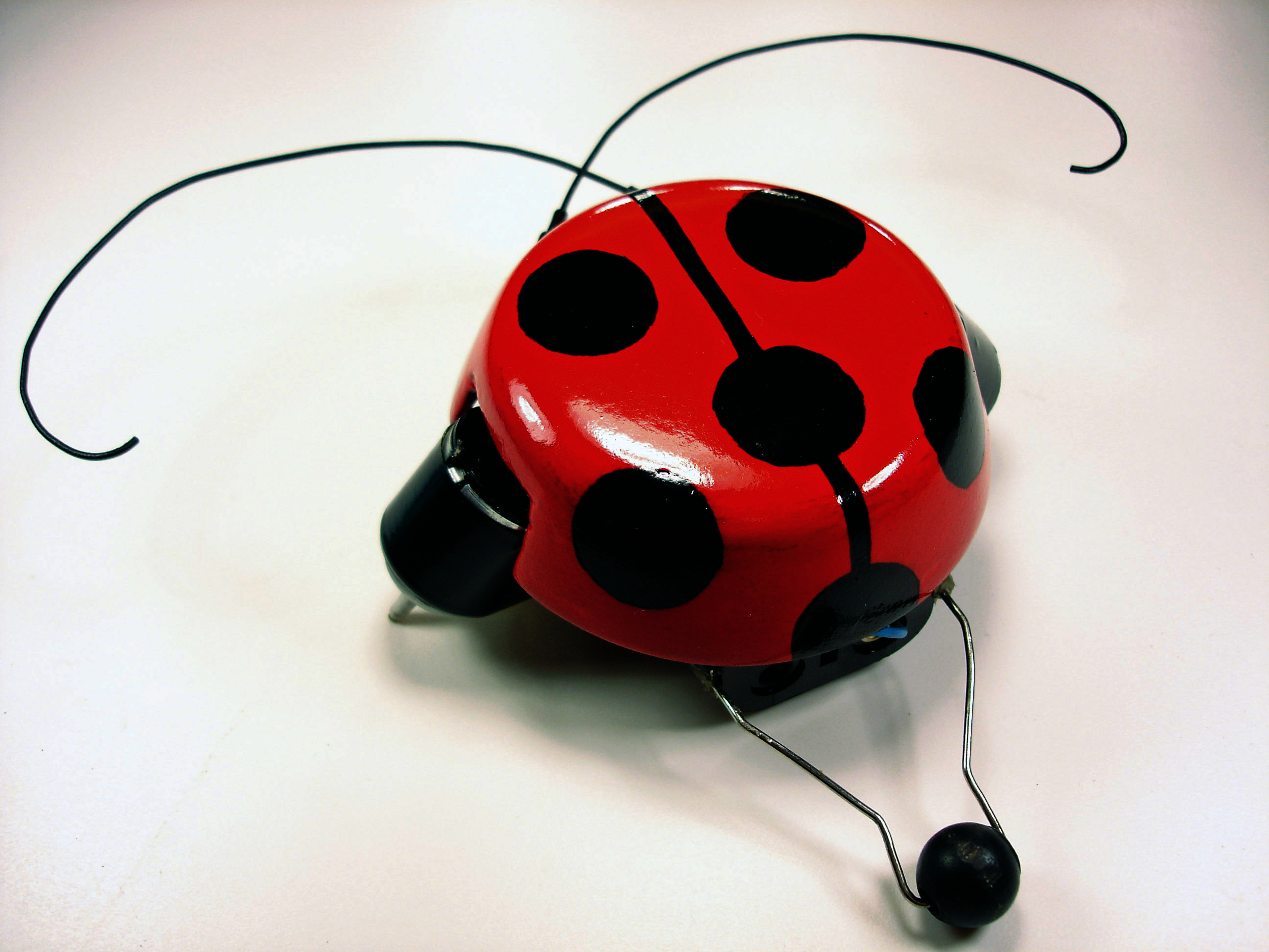
After sanding the lid smooth, give it a couple coats of primer, and then paint it. To make a ladybug beetle pattern, I started by painting the whole thing black (I also painted the antennae black). Then I used a dime as a template to cut round pieces of masking tape, which I applied to the lid along with a thin masking tape centerline.

I painted a glossy red over everything, and then removed the tape. For the final polish, I sanded the whole thing with very fine sandpaper and some water, which gives a glossier finish than sanding dry; this is a trick I learned from a friend who was restoring a guitar. I let everything dry and gave it 2 coats of clear varnish.

To connect the shell to your robot, you can glue it directly to the battery holder, or you can use magnets; glue one inside the lid and another in a matching position on the battery holder. This lets you remove the shell easily, to show your friends the insides of your biomech bug!

Conclusion

This project originally appeared in MAKE Volume 12.

Related Posts on Make: Online:

How-To Tuesday: Make a Beetlebot

http://blog.makezine.com/archive/2009/03...

Mousey the Beetlebot

http://blog.makezine.com/archive/2008/12...