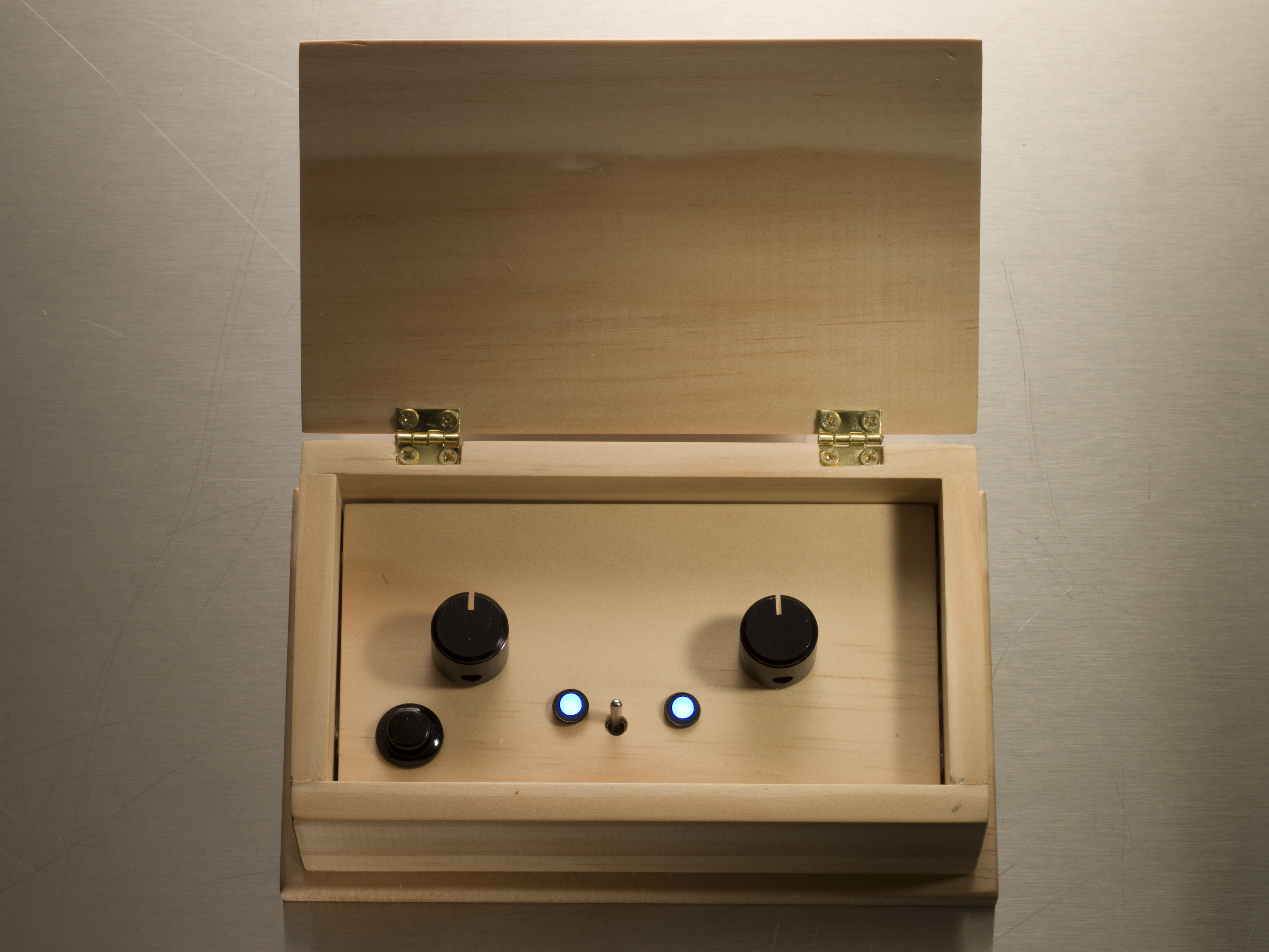
The Luna Mod is an easy and fun instrument that will have you making great-sounding loops in no time. Rather than sampling input like a traditional loop station, the Luna Mod synthesizes its own sounds, and you play it using two knobs and one button.

I based the Luna Mod on the Wicks Looper, which I sell on Etsy, but it’s designed to be even simpler to build and play, without any complicated functions that would never get used. One knob controls the sound generated, the other controls the tempo of the loop, and the button writes the current sound into the ongoing loop. The variety of sounds you can get from these three controls is amazing.

You don’t need any special or expensive tools to build the Luna Mod, and it was designed for hackability. Its handy, built-in programming port lets you easily upload new firmware to the microcontroller chip, in order to change the sounds the instrument produces and which variables are tied to which controls.

YouTube player

Check out more Weekend Projects.

Project Steps

Populate the circuit board

Luna Mod schematic

Take a 26×16-hole piece of stripboard (use a sharp hacksaw as necessary to cut to size, then sand the edges smooth). The copper strips should run the long way.

Cut, strip, and solder 13 solid-core jumper wires between the following points on the board: (5,1 to 5,3), (5,15 to 5,16), (7,10 to 7,11), (7,13 to 7,15), (11,5 to 11,11), (13,5 to 13,7), (14,4 to 14,9), (16,8 to 16,14), (17,9 to 17,11), (19,10 to 19,12), (19,14 to 19,15), (21,9 to 21,14), and (22,8 to 22,13).

To identify holes on the board for placing components, I use grid references of the form (x,y), where (1,1) is the top left hole of the non-solder pad side, and the board’s long edge and copper strips run along the x-axis.

On the shorter jumpers you can remove all the insulation on the wires.

Populating the board

Turn a sharp 1/8″ drill bit by hand to make breaks in the board’s copper traces at these points: (5,12), (8,3), (8,11), (8,13), (11,3), (14,11), (14,12), (14,13), (14,14), (16,3), (17,14), (17,16), (19,8), (20,12), (24,6), (24,10).

Remember to count the x-coordinate from right to left when the board’s copper side is facing you.

Solder the resistors onto the stripboard: 1kΩ (18,12 to 18,16) and (25,12 to 25,16); 10kΩ (2,12 to 2,16), (9,7 to 9,14), (10,3 to 10,13), and (21,3 to 21,7); and 22kΩ (3,12 to 7,12).

Adding additional components

Solder in the 8-pin IC socket with Pin 1 at (12,11) and Pin 8 at (15,11).

Solder in the 2 caps: 10nF (23,12 to 23,14) and 100nF (20,14 to 20,16).

Solder in the voltage regulator, Pin 1 to (3,5) and Pin 3 to (3,3).

Installing the LEDs

Trim the LED leads to ½” (14mm) to keep them long enough to poke up through the panel, but keep track of which legs are positive (anode, with the longer leg) and which are negative (cathode, shorter and marked by a flat part in the plastic).

Solder one LED with its (+) leg at (9,3) and (–) leg at (9,4), and the other with (+) at (18,3) and (–) at (18,4).

The on/off toggle switch legs are too wide to fit directly into the PCB holes, so use a 1/16″ drill bit to extend the holes into small slots at (14,1), (14,2), and (14,3).

Fit and solder the switch into place.

In go the pots

For the potentiometers, use the 5/16″ bit to enlarge the holes at (1,6), (1,10), (26,6), and (26,10). Locate Pin 1 on each of the pots; it’s the rightmost pin as you face the pins with the pot shaft pointing up.

Fit the pots’ mounting tabs into the enlarged holes with Pin 1 of one at (4,9) and Pin 1 of the other at (23,7). Solder into place.

For the programming socket, cut 3 wires, ideally of different colors, about 3½” (or 9cm) long. Solder one end of each to (1,11), (1,12), and (1,13).

Remove the 1/8″ stereo jack cover, slip it over the 3 wires, and solder the wires to the jack’s contacts for the plug’s sleeve (inner), ring (middle), and tip (end), respectively. Replace the cover.

Wiring the pushbutton and audio jack

Solder 2 wire leads for the pushbutton about 7″ (or 18cm) long at locations (1,14) and (1,15).

You’ll solder the pushbutton to these 2 loose wires after fitting it into the front of the panel.

Solder 2 wires about 7″ (or 18cm) long to the PCB at (26,12) and (26,14). Solder the other ends to the panel-mount mono audio jack’s tip (signal) and sleeve (ground) contacts, respectively.

Finishing up the electronics

Solder the 9-volt battery clip to the board, red (+) to (1,2) and black (–) to (1,4).

Plug the Picaxe 08M into the IC socket with pin 1 at upper left, nearer the LEDs.

The circuit board is now finished and ready to fit into the control panel.

Building the case

Using 3/8″ board, cut two 5½”×1 5/8″ side pieces and two 2½”×1 5/8″ end pieces. (Using 8mm boards, cut pieces 140mm×40mm and 65mm×40mm.)

For the base, cut a piece 5 7/8″×3 5/8″ (or for 8mm wood, 150mm×90mm.)

For the lid, cut a piece 5½”×3¼” (or for 8mm wood, 140mm×82mm.)

For the control panel, cut a piece 4¾”×2½” (or for 8mm wood, 124mm×65mm.)

Use sandpaper and a sanding block to put a small bevel around the top edges of the base and lid pieces.

Assembling the sides and ends

Using a sash clamp or band clamp, glue and clamp the pieces together into a box shape, with the end pieces abutting the sides. Let dry.

Drill a hole in the bottom right rear corner of the enclosure for the audio jack. I used a 23/64″ bit 20mm from the side and 8mm from the bottom, although anything in this general range will do. Countersink the hole slightly with a bigger drill bit.

Using wood clamps, glue and clamp the sides of the case centered onto the base piece. Let dry.

Attaching the lid

Place the hinges on the lid about 3/8″ (or 1cm) in from the side, mark the screw holes with a pencil, and drill 1/16″ holes for the hinge screws.

Screw the hinges to the lid.

With the lid in place, use a pencil to draw around the position of the hinges on the rear side piece.

In go the the hinges

Use a small chisel to cut a recess into the wood in the shape of the hinges about 1/8″ (3mm) deep.

Mark and drill 1/16″ holes for the hinges in the recesses, and screw on the lid.

Drilling the control panel

Using your completed circuit board as a template, drill the holes to fit in the control panel: ¼” for pots and LEDs, and 3/16″ for the toggle switch. Also drill a 15/32″ hole at lower left for the pushbutton.

Finish the wood by rubbing it with beeswax or polish. Now the box is ready for fitting the electronics.

Assemble the panel hardware

Fit the plastic LED holders to the front panel. To help the LEDs fit, I snipped the two longer holding clips off.

Press the circuit board onto the back of the control panel, fitting all components through their holes.

Attaching the switches

When the circuit board is in the right spot, tack the toggle switch to the wood with a little hot glue.

Fit the pushbutton switch through its hole in the panel front. Bend its solder tabs back, and solder the push-button switch wires to the solder tabs. Add hot glue to hold the pushbutton in place.

Attaching audio jack and battery

Fit the ¼” panel-mount audio jack to the case and hot-glue it in place.

Use hot glue to secure the audio jack programming port along the top edge of the circuit board.

Clip a 9V battery onto the battery clip.

Completing the hardware

Hold the battery under the right side of the control panel and fit the panel into the case.

Screw the knobs onto the potentiometers with their included “grub screws” (set screws).

Your hardware is now completed.

Program the Luna Mod

Download and install the free Picaxe Programming Editor Software from http://rev-ed.co.uk/picaxe, under the Software tab.

Download the BASIC program file Luna_Mod.bas from http://cdn.makezine.com/make/26/Luna_Mod.bas.

Lift up the control panel and connect the Picaxe programming cable between the Luna Mod programming port and your computer.

Launch the Picaxe Programming Editor Software. Select File ⇒ Open, then select Luna_Mod.bas from the folder you downloaded it into.

With the Luna Mod connected to the computer, power it up using its on/off switch.

Press the computer’s F5 key to compile and load the Luna_Mod.bas program onto the Luna Mod. After the program has transferred, you should see a “Download was successful!” message box. Then disconnect the programming cable and refit the control panel.

Your Luna Mod is ready to play!

Test the Luna Mod

When you turn on the Luna Mod, the power light should come on, and the Tempo LED should flash.

Plug some headphones in and press the Write button — you should hear some noise.

Turn the Sound knob while pressing the button, and the sound should change. Now move the Tempo knob — you should hear the loop getting faster and slower. If all that works, you’re good to go.

Otherwise, check your wiring against the Luna Mod schematic diagram found at the beginning of this project.

Playing the Mod Sounds of the Luna Mod

Playing the Luna Mod is a matter of experimentation. Keep in mind that you can always create breaks in the sound by turning the Sound knob completely counterclockwise.

I had an enormous amount of fun learning how to play the Luna Mod because I’d never played an instrument like it before. I usually start with a basic rhythm that I set up by moving the Sound knob quickly clockwise while pressing the Write button. Then I add tones and blips by putting the Sound knob into various spots and quickly pressing the Write button once or twice. With this basic rhythm in place, you can let it repeat or keep adding and overwriting tones as desired.

Another trick for playing the device is to record a loop with the Tempo knob at its slowest speed, then increase the tempo for a fast, highly detailed loop.

When I set up the Luna Mod for recording, I usually connect it directly to my mixer/recorder. For a more refined sound, I sometimes plug it into a reverb pedal, then a delay pedal, then the mixer/recorder.

Mod Your Luna Mod!

The Luna Mod program only uses 81 of the 256 bytes available on the Picaxe 08M’s onboard memory. So with the Luna Mod’s built-in programming port, you have lots of room to modify and hack the software to make new sounds and functions.

Enjoy, and let us know what you come up with!

Conclusion

This project first appeared in MAKE Volume 26, page 80.