


Since an electromagnetic telephone receiver can double as a microphone, can a semiconductor light detector double as a light emitter?
That question was on my mind when I was a high school senior in 1962. Back then I didn’t know that quantum effects in a semiconductor are unrelated to the electromagnetic operation of a telephone receiver. If I’d known that, I never would have connected a spark coil across the leads of a cadmium sulfide photoresistor to see if it would emit light. It did — a soft green glow punctuated with bright flashes of green.
During college I found that a silicon solar cell connected to a transistor pulse generator emitted flashes of invisible infrared that could be detected by a second solar cell. In 1972, I used near-IR LEDs and laser diodes to send and receive voice signals, through the air and through optical fibers. Later I experimented with two-way optocouplers made by taping a pair of LEDs together so they faced one another.
In 1988, I tried LEDs as sunlight detectors. They worked so well that the first homemade LED sun photometer I began using on Feb. 5, 1990, is still in use today.
Why Use LEDs As Sensors?
Silicon photodiodes are widely available and inexpensive. So why use LEDs as light sensors?
- LEDs detect a narrow band of wavelengths, which is why I call them spectrally selective photodiodes. A silicon photodiode has a very broad spectral response, about 400nm (violet) to 1,000nm (invisible near-IR), and requires an expensive filter for detecting a specific wavelength.
- The sensitivity of most LEDs is very stable over time. So are silicon photodiodes — but filters have limited life.
- LEDs can both emit and detect light. This means an optical data link can be established with only a single LED at each end, since separate transmitting and receiving LEDs aren’t needed.
- LEDs are even more inexpensive and widely available than photodiodes.
Drawbacks of LEDs As Light Sensors
No sensor is perfect.
- LEDs are not as sensitive to light as most silicon photodiodes.
- LEDs are sensitive to temperature. This can pose a problem for outdoor sensors. One solution is to mount a temperature sensor close to the LED so a correction signal can be applied in real time or when the data are processed.
- Some LEDs I’ve tested do gradually lose their sensitivity.
LEDs Detect Specific Colors of Light
The typical human eye responds to light with wavelengths from around 400nm (violet) to about 700nm (red). LEDs detect a much narrower band of light, having a peak sensitivity at a wavelength slightly shorter than the peak wavelength they emit. For example, an LED with a peak emission in the red at 660nm responds best to orange light at 610nm.
The spectral width of light emitted by typical blue, green, and red LEDs ranges from about 10nm—25nm. Near-IR LEDs have a spectral width of 100nm or more. The sensitivity of most LEDs I’ve tested provides ample overlap to detect light from an identical LED.

Figure A shows the spectral response of 7 blue, green, red, and near-infrared LEDs that replace the usual silicon photodiodes and filters in my modified Multi-Filter Rotating Shadowband Radiometer, used for solar spectroscopy.
Blue and most green LEDs are made from gallium nitride (GaN). The brightest red LEDs are made from aluminum gallium arsenide (AlGaAs). The LEDs used in near-infrared remote controllers are also AlGaAs devices; their peak emission is about 880nm and peak detection around 820nm.
Older remote controllers used gallium arsenide compensated with silicon (GaAs:Si). These LEDs emit at about 940nm, which makes them ideal for detecting water vapor, but they’ve become very difficult to find.
In my experience, the sensitivity of red “super-bright” and AlGaAs LEDs and similar near-IR LEDS is very stable over many years of use. Green LEDS made from gallium phosphide (GaP) are also very stable. However, a blue LED made from GaN has declined in sensitivity more than any LED I have used.
NOTE:
- This does not apply to white LEDs, which are blue-emitting LEDs coated with a phosphor that glows yellow and red when stimulated by blue from the LED. The merging of the blue, yellow, and red provides white light. While a white LED can detect blue light, a blue LED is a much better choice.
Basic LED Sensor Circuits


You can substitute an LED for a standard silicon photodiode in most circuits. Just be sure to observe polarity. Also, remember that the LED isn’t as sensitive as most standard photodiodes and will respond to a much narrower band of light wavelengths.
For best results, use LEDs encapsulated in clear epoxy and try a few experiments first. These will help you understand how the detection angle of an LED used as a sensor matches its emission angle when used as a light source:
- Use standard couplers to attach LEDs to plastic optical fiber, or attach them directly using this method (Figure B): Flatten the top of the LED with a file, clamp it securely, and carefully bore a small hole just above the light-emitting chip. Insert the fiber and cement it in place.
- Connect the leads of a clear encapsulated red or near-IR LED to a multimeter set to indicate current. Point the LED toward the sun or a bright incandescent light, and the meter will indicate a current (Figure C).
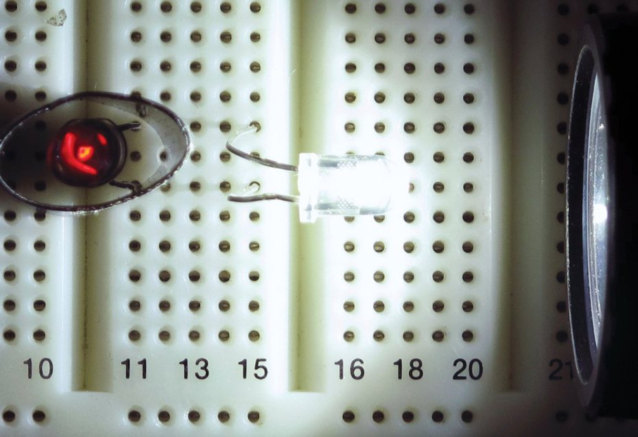
- Use one LED to power a second LED. Connect the anode and cathode leads of 2 clear encapsulated super-bright red LEDs. When one LED is illuminated with a bright flashlight, the second LED will glow. Heat-shrink tubing is placed over the glowing LED to block light from the flashlight. You can see this working in the photo at the top of the article.

LEDs have a much smaller light-sensitive surface than most silicon photodiodes, so they’re more likely to require amplification. Inexpensive operational amplifiers are ideal. Figure D shows a simple circuit I often use to convert the photocurrent from an LED into a proportional voltage. The Linear Technology LT1006 single-supply op-amp (IC1) provides a voltage output that’s almost perfectly linear with respect to the intensity of the incoming light. The gain or amplification equals the resistance of the feedback resistor (R1). Thus, when R1 is 1,000,000 ohms, the gain of the circuit is 1,000,000. Capacitor C1 prevents oscillation.
Many other op-amps can be substituted for the LT1006, but most of them require a dual-polarity power supply. If you use one of these, connect pin 4 directly to the negative supply. Connect pin 3 and the cathode of the LED to ground (the junction between the minus side F of the positive supply and the positive side of w the minus supply).
Going Further
The best way to come up with new applications for LEDs operated as photodiodes is to experiment with the applications I’ve described here. When I was doing this back in the 60s, I had no idea those simple experiments would lead to two-way communication over a single optical fiber and several kinds of instruments to measure the atmosphere that I’ve been using for more than 23 years.
This article first appeared in MAKE Volume 36, page 136.
For more of Forrest M. Mims III’s articles and books concerning “LEDs as photodiodes”, please visit forrestmims.org/publications.html.


