M36_Proj_SpanglerFusorOpener4x3

Nuclear fusion is the process of squeezing two atoms together so tightly that their nuclei fuse, creating a heavier atom and releasing a blast of energy. Fusion creates the inferno inside the sun — and the hydrogen bomb — but no one has yet harnessed its enormous power for peaceful uses.

They’ve tried, of course, with experiments ranging from massive tokamak reactors to modest laboratory setups. In 1989, physicists Martin Fleischmann and Stanley Pons announced they’d achieved “cold fusion” of hydrogen into helium at room temperature, only to face withering scorn when others failed to replicate their results.

Luckily, DIY nuclear engineers can achieve honest-to-goodness “hot fusion” right at home by making a Farnsworth-Hirsch fusion reactor, or fusor for short.

YouTube player

This mini fusor is a demonstration version — while it generates only insignificant quantities of fusion products, it does show how inertial electrostatic confinement (IEC) reactors use kinetic energy to cause fusion. It’s also a good introduction to high-voltage power supplies and vacuum systems. The skills the project imparts will help you tackle bigger fusors and other projects involving plasma and high-energy physics.

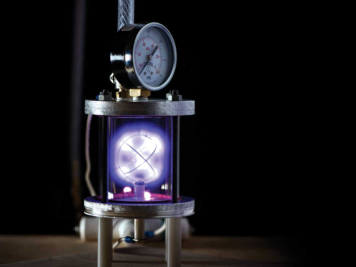
Plus, the fusor just looks totally cool. An eerie purple-blue glow emanates from the reactor, and a really well-made fusor can produce a mesmerizing phenomenon called a “star in a jar.”

Curious? Read on…

Warning

This project uses high voltages at potentially lethal currents. A high-vacuum apparatus may implode if improperly handled. This device may produce ultraviolet and x-ray radiation. Do not attempt to build or operate it unless you are capable of safely using high voltage and vacuum equipment.

How It Works

nuker_diagram_v4
The typical Farnsworth-Hirsch fusor has two concentric electrical grids inside a vacuum chamber: an inner grid charged to a high negative potential, and an outer grid held at ground potential. Our benchtop version has a stainless steel wire inner grid, and uses the aluminum chamber walls as the outer grid.

A variac controls the AC mains voltage input to a neon sign transformer, which steps up standard 110V AC to the 10kV range. A homemade rectifier converts AC to DC power to charge the grid.

A vacuum pump evacuates the chamber to a pressure of about 0.025mm of mercury, clearing the playing field so the few remaining gas molecules can accelerate without premature low-energy collisions. A vacuum gauge indicates the pressure inside.

High voltage across the grids causes gas molecules to ionize; that is, they lose an electron and become positively charged. Electrostatic forces then accelerate the ions — mainly O2+, N2+, Ar+, and H2O+ — toward the high negative charge at the center. Some ions collide; those that miss the first time are arrested by the electric field and re-accelerated toward the center for another go.

Low-power fusors produce a beautiful purple ion plasma “glow discharge” similar to plasma globes and neon signs. In high-power fusors, the inertia of the ion collisions squeezes hydrogen atoms tight enough to fuse, hence the term inertial confinement.

High-power fusors typically fuse deuterium (D or 2H) into helium and tritium. Deuterium is a hydrogen isotope whose nucleus contains a neutron in addition to the usual single proton. It occurs naturally in very low concentrations, primarily as hydrogen deuteride (HD) but also as “heavy water” (D2O), “semiheavy water” (HDO), and deuterium gas (D2). Only 1 in 6,000 hydrogen atoms is deuterium. Tritium (a hydrogen atom with two neutrons and one proton) is even rarer.

When two deuterium atoms fuse they create a high-energy helium-4 atom, which stabilizes itself by releasing a proton, a neutron, or a gamma ray. This release leaves behind a tritium atom, helium-3 atom, or helium-4 atom, respectively.

Fusor Nation

The fusor was developed in the 1960s by Philo T. Farnsworth, who also invented television. It’s popular with DIY experi-menters because it’s easy to build and can reliably produce fusion reactions.

Fusors have yet to produce useful power, but they can be dangerous. They require high voltages and can produce harmful ultraviolet, x-ray, gamma, and free neutron radiation.

IEC reactors are currently being studied at MIT, the University of Wisconsin-Madison, University of Illinois, Los Alamos National Laboratory, and EMC Corporation, among other labs.

Project Steps

Cut the chamber parts.

Use the hole saw to cut two 4″-diameter blanks from the aluminum bar stock. Use the slowest speed on your drill press and use WD-40 as cutting fluid. It’s still going to make a lot of horrible noise. Clean up rough edges with a file, taking care not to scratch the surface of the blanks.

Cut the chamber parts (cont'd).

Print and cut out the flange templates. Stack the 2 aluminum blanks with the template on top and bolt them together concentrically with a 1-1/2″-long 1/4-20 bolt. Use masking tape on the contacting surface to prevent scratches, and to hold the template in place. Center-punch all holes and remove the template.

Cut the chamber parts (cont'd).

Drill out the 4 bolt holes (leave the offset hole for later), first with a 1/8″ bit and then again with a 1/4″ bit. This is called step drilling and it makes drilling large, accurate holes much easier.

Make sure the blanks don’t shift when drilling. Before you separate the flanges, use a center punch or marker to make witness marks on their edges so you can line up the 2 hole patterns correctly every time you assemble the fusor chamber.

Cut the chamber parts (cont'd).

Drill out the center bottom flange hole to 3/8″ (first image) and test-fit the ceramic tubing. It should be a close fit.

If it’s too tight, tape a strip of sandpaper to a nail, wrap the sandpaper tightly around the nail, chuck it in a power drill, and use it to expand the hole just enough that the ceramic tube fits snugly.

On the top flange, drill the center hole and the offset hole to 7/16″ using the step drill method (second image).

Clamp the flange in a vise, using tape or shims to prevent marring, and carefully tap the two 7/16″ holes you just drilled to 1/4-18 NPT (third image). Note that this is a tapered thread.

Cut the chamber parts (cont'd).

Following the templates, use a hobby knife to cut 2 gasket rings (2-1/2″ ID × 3-1/8″ OD) from sheet rubber (first image).

Use a rotary tool and diamond cutoff wheel to cut a 2″ length of ceramic tubing. Sand the rough edges smooth

Install the feed-through.

Using 24-hour epoxy, glue the aluminum standoff into the ceramic tubing, taking care not to get any glue in the threads. You may need to file or sand down the outside of the standoff to make it fit. Let the epoxy dry 24 hours. This is your high voltage feed-through.

Using a healthy amount of epoxy, glue the feed-through into the center hole in the bottom flange, making sure it protrudes 1/2″ into the chamber. Again, keep glue out of the threads.

Add the vacuum ports.

Apply Teflon tape to the threads and then thread the vacuum gauge into the center hole in the top flange and the barbed hose fitting onto the offset hole. Tighten securely with a wrench.

Fabricate the grid.

Cut a 12″ length of 1″ PVC pipe and then drill a 1/16″ hole in the middle.

Cut 48″ of stainless steel wire and anchor one end securely in a vise or clamp. Thread the other end into the hole in the PVC pipe and neatly roll the wire around the pipe while applying constant firm tension.

Release the wire from the anchor point and clip it off the pipe, being careful to keep the wire from springing back. You’ll be left with a small coil of wire with 10–12 turns, about 1-5/8″ in diameter.

Fabricate the grid (cont'd).

Clip 3 rings off the coil. Solder one ring closed using silver solder and a MAPP gas blowtorch.

Link a second ring through the first, solder it closed, and carefully solder the 2 rings together so they’re at right angles.

Stretch the third ring over the first 2 to form a spherical cage with 8 equal openings. Trim it to size and solder it in place.

Finally, solder a #10-32 stainless steel machine screw to the outer ring, midway between two of the existing solder joints.

Make the base.

Cut an 8″×8″ square of 1/2″ plywood. Use one of the flanges as a guide to lay out the 4 bolt holes.

Drill 1/4″ holes and hammer in the 4 T-nuts. Adhere a rubber foot in each corner, on the same side as the T-nuts.

Assemble the fusor chamber.

Apply thread-lock to the threaded steel rods and screw them into the T-nuts until they’re flush with the T-nut flanges, as seen in the first image.

Slip a nylon spacer over each rod, then stack the bottom flange on top of the spacers; make sure the longer end of the high-voltage feedthrough protrudes downward.

Assemble the fusor chamber (cont'd).

Wearing latex gloves, wipe the surface of the flange with alcohol and wait for it to dry.

Apply vacuum grease to both sides of a rubber gasket, carefully center the gasket on the bottom flange, and thread the spherical inner grid cage onto the end of the high-voltage feedthrough.

Assemble the fusor chamber (cont'd).

Wearing a fresh pair of gloves, clean the glass cylinder with alcohol and carefully place it on top of the gasket. Apply vacuum grease to both sides of the second gasket and lay it on top of the glass cylinder. Try to avoid getting any grease on the sides of the glass.

Now clean the top flange with alcohol and stack it on top of the second gasket, making sure the flange witness marks line up. Finish it off with four 1/4-20 nuts. The nuts should be just finger-tight, only slightly deforming the rubber gasket. Overtightening them may crack the glass!

Plumb your fusor.

Cut a 2′ length of 3/8″ ID reinforced vinyl tubing, slide the 2 hose clamps onto it, and fit the hose over the barbs on your vacuum pump and fusor chamber. Tighten the clamps over the hose and barbs.

Follow the instructions provided by the manufacturer of your vacuum pump to get it operating correctly (vacuum oil, power, venting, etc.). Vacuum pumps vary, and you may have to install additional plumbing to fit a male barbed adapter sized for 3/8″ ID tubing.

Make the high-voltage rectifier.

Solder the 2 high-voltage diodes together, making sure the ends with the white bands are facing away from each other.

Cut three 2″ lengths of 16 AWG stranded wire, strip 1/4″ of insulation off the ends, and bend each wire into an S shape. Solder one wire to each free end of the diodes and the third wire to the joint between the two.

Crimp a ring terminal to the free end of each of the 3 wires.

Make the high-voltage rectifier (cont'd).

Drill a #21 (or 4mm or 5/32″) hole into the top center of three 1/2″ PVC pipe caps and “tap” the holes with a #10-32 screw

Feed the diode assembly through a 1/2″ PVC tee union so that the middle wire goes out the side junction and the other 2 wires go out the ends.

Make the high-voltage rectifier (cont'd).

Cut three 1-1/2″ lengths of 1/2″ PVC pipe and glue them into the ends of the tee, around the wire leads.

Pass a #10-32 machine screw through each ring terminal and screw it into the threaded hole in each cap.

Glue the 2 side caps on, but not the top one yet.

Make the high-voltage rectifier (cont'd).

Place the tee in a vise with the opening facing up, and carefully pour in mineral oil until it’s full to the bottom of the branch.

Loosen the vise, rock the tee gently side to side to make sure there aren’t any trapped air bubbles, and then fill it all the way up. Screw the remaining ring terminal to the inside of the top cap and glue the cap in place, sealing the tee permanently.

Wire the transformer.

If you’re lucky, your neon sign transformer has a power cord attached. If not, open up a male plug with a ground prong and wire one end of a 3-wire AC power cord into it. The green wire goes to the ground prong. The black and white wires go to the hot and neutral prongs — it doesn’t matter which is which.

On your NST there should be 2 large ceramic standoffs; these are your high-voltage outputs. Ignore them for now. We’re interested in the 2 smaller input terminals and the single ground screw.

Separate the 3 cord wires so the black and white wires reach the input terminals and the green wire reaches the ground screw. Strip ¼” of insulation off the wire ends and crimp a spade terminal to each, then affix the wires to the corresponding terminals. Again, the orientation of the black and white wires doesn’t matter — it will work either way.

Wire the fusor.

Cut three 12″ lengths and one 24″ length of high-voltage wire, strip 1/4″ of insulation off the ends, and crimp a spade connector onto both sides of each one.

Attach a 12″ wire between each of the 2 high-voltage terminals on the NST and one of the 2 side terminals on the rectifier. Connect the third 12″ wire between the top of the rectifier and the fusor’s high-voltage feed-through using a 1/2″-long #10-32 screw.

Finally, connect the 24″ wire to one of the top studs holding the fusor together, using the nut to hold it on the threaded rod. Attach the other end to the ground screw on your NST.

Test the vacuum.

When working with glass vacuum chambers, always test the chamber from behind a safety barrier first. I used a door with a window and just ran the power cord under the door.

Plug in the vacuum pump and watch from safety as the needle on the vacuum gauge goes to 0. Leave the pump running for 5 minutes. If it doesn’t implode during that time, it should be OK for normal use if treated gently.

Turn off the vacuum pump and allow the system to return to ambient pressure before handling or storing the fusor.

Working with high voltage.

Our fusor is a relatively low-power version, with its components grounded to minimize the danger of shock. Still, accidents happen. Here’s what you need to know to stay safe.

Electricians have a saying: Volts hurt, amps kill. Current is more dangerous than voltage — just 10–20 milliamps (mA) of alternating current (AC) can cause muscle contractions that prevent you letting go of the electrified object, and 70mA–100mA can cause heart fibrillation and death.

Household AC wall power is typically 120 volts at a lethal 15 amps of current. And it alternates at 60Hz frequency, which can also cause fibrillation. It’s very hazardous.

The variable transformer modulates wall power up to 140V AC at 5A current — lower, but still a real electrocution hazard.

Next, the neon sign transformer steps up the voltage to a high 12,000V AC and slashes the current to 30mA — unlikely to cause fibrillation but still above the “let-go threshold.”

Finally, the rectifier converts AC to DC —

direct current — at 6,000V, 30mA. That’s half the voltage of the NST output, and falls below the let-go threshold for DC current (about 75mA). But it can still be deadly, as DC causes worse contractions and tissue burns than AC.

So be sure to wire your fusor correctly, and avoid touching any part of it during operation except the variable transformer knob. And when in doubt, ask an expert before proceeding.

Conclusion

Running Your Fusor

Plug the transformer’s power cord into the outlet on your variac, then plug the variac into the wall outlet. Don’t switch the variac on yet.

Turn on the vacuum pump, wait for the gauge to reach 0, then wait another 2–5 minutes to reach deeper vacuum. Leave the pump running. Now switch on the power for the variac and slowly turn the knob, increasing the voltage fed through the transformer.

If everything works, you should see a bright purple discharge inside the chamber, and as you turn up the voltage a defined plasma ball will form inside the grid, with the occasional plasma beam leaching out through one of the grid openings. If you’ve built carefully, you may achieve the coveted “star in a jar”: a glowing plasma ball with fine plasma lines radiating out in all directions through the grid openings.

Congratulations, you have successfully built a demonstration fusion reactor based on the principle of inertial electrostatic confinement!

Never run your fusor for extended periods of time. A minute or two is plenty. Plasma beams escaping from the core may spot-heat the glass and cause it to implode. Make sure that you and everyone nearby wears ANSI-approved safety goggles whenever the cylinder is under vacuum.

Warnings

Glass vacuum chambers can implode. Do not operate the vacuum system without safety goggles. Reminder: High voltage and current can injure or kill. Fusors may generate harmful radiation. Do not attempt to build or operate this fusor unless you understand the risks and are capable of safely using high voltage and vacuum equipment. Do not run this device at more than 12kV rectifier input.

Troubleshooting

When you first ignite your reactor, you may see sparks and arcs on the inner grid. As long as these don’t persist in one spot, it’s fine — just bits of dust and debris burning off, and after a while the sparks will stop. But if arcing persists, you’ve probably got carbon deposits, which will continue to arc. This can be dangerous, so stop and clean the chamber thoroughly before proceeding.

If the glow discharge is deep purple, the seals are probably leaky; check the gaskets and reapply vacuum grease. With a good vacuum, you should see a bright, almost-blue purple glow.

This project first appeared in MAKE Volume 36, page 90.