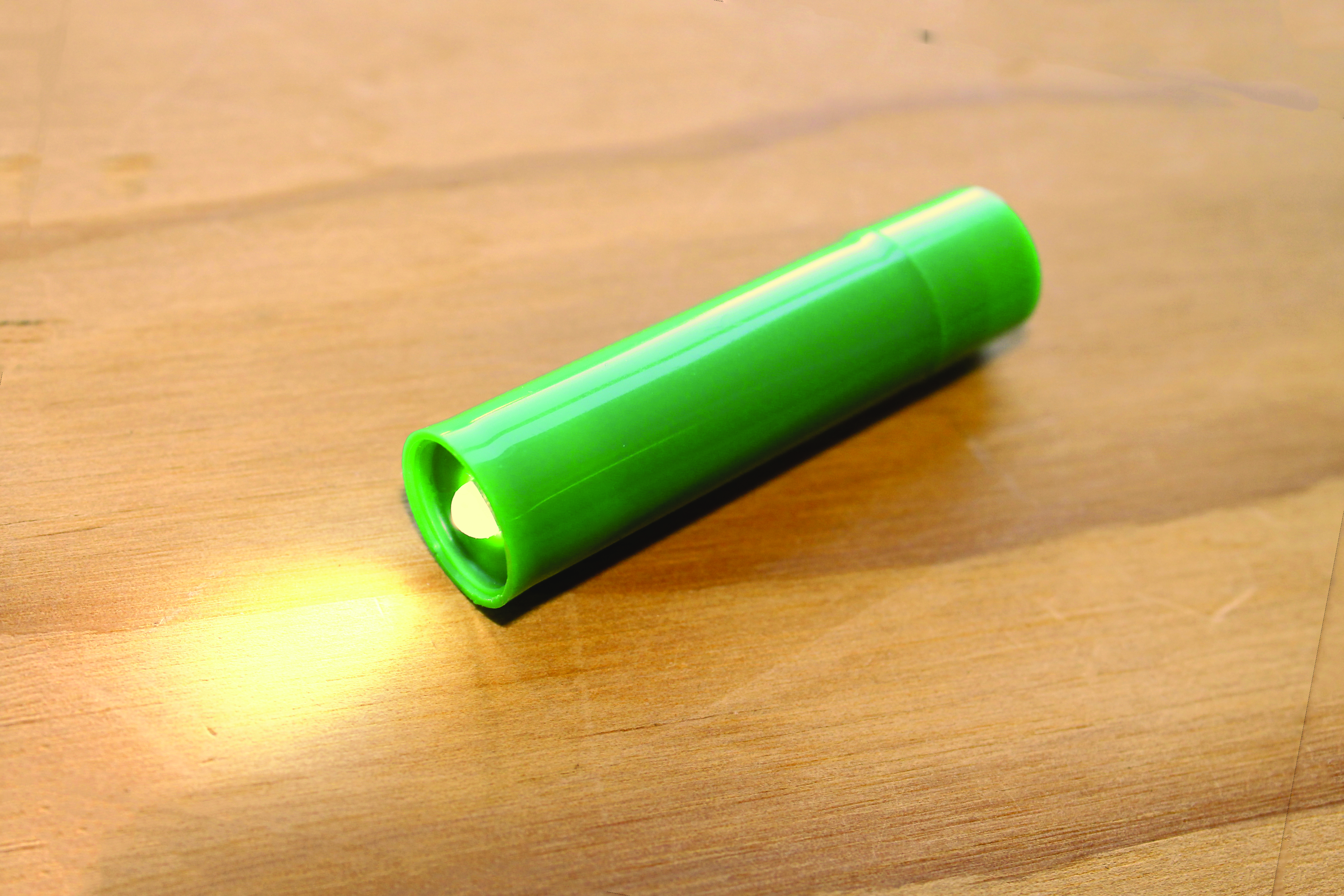
M37_Projects_ZombieFlashlight_Opener

There’s a well-known circuit, commonly called a “joule thief,” that can power a 3V white LED with a single 1.5V battery. Not only can this circuit boost the voltage high enough to light the LED, it can also do it with a battery that’s considered dead, “stealing” the last bits of energy in the cell.

I built my first joule thief on a breadboard with what was then a hard-to-come-by white LED. (Now you can find them all over.) I was able to pull all the other parts from my parts bins. This was my first circuit using an inductor, so I was glad I had saved all those ferrite bits! I even had a bin of mostly “dead” batteries that I hadn’t recycled yet. I felt like Victor Frankenstein or George Romero!

Scrounging and reusing materials is an important part of how I make things. (I’m also very cheap.) I always feel an extra bit of pride when I can show off a cool project and say: “… and I built it all from scrap parts!”

Once I had the breadboard version working, I thought about what I was going to put it in. I really wanted this flashlight to be a nice everyday carry, like my old AAA Maglite. I found a few tutorials for stuffing all the parts into a miniature incandescent bulb housing but that didn’t do it for me. While I was searching, I found a used-up tube of lip balm in an old pair of pants. Could I fit it all in there and an on/off switch besides? Only one way to find out!

Here’s a schematic diagram that shows how it goes together:
JouleThiefSchem.bmp
A. White LED
B. NPN transistor
C. 1K resistor
D. Transformer (wound ferrite bead)
E. AAA battery
F. On/off switch

People who understand electronics a lot better than I do have described how this circuit works — in essence, it’s a blocking oscillator, a transistor-transformer duo that rapidly switch each other on and off — but you don’t need to know the theory to build one. It’s easy enough!

What will the next generation of Make: look like? We’re inviting you to shape the future by investing in Make:. By becoming an investor, you help decide what’s next. The future of Make: is in your hands. Learn More.

Project Steps

Prepare the lip balm tube.

Remove the cap and peel off the label.

Turn the adjustment knob at the bottom of the tube until the carriage is at the open end. Pull the carriage out of the tube with needlenose pliers and discard it.

Pry the adjustment knob off and discard it.

Clean the tube and cap thoroughly with hot soapy water and a toothbrush. Make certain no balm remains in the cap.

Wind the transformer.

Cut off at least 2 feet of magnet wire from the spool, or unsolder a small transformer from some scrap electronics and unwind the wire from the bobbin until you’ve got at least 2 feet.

Thread one end of the wire through the center of the ferrite bead, leaving 1″ or so behind. Loop the long end back through the same direction 5 times.

Wind the transformer, cont'd.

Stop and twist a couple inches into a loop.

Continue looping in the same direction 5 more times.

Using a knife or sandpaper, scrape the enamel coating off both ends and the loop. Tin each with solder. (Some coatings can be soldered through, but check with a scrap of wire beforehand.)

Make the copper bar.

Strip the insulation from the 10-gauge wire. Flatten the wire into a bar with a hammer and anvil. This will make the wire easier to fit in the tube and also harden it.

Bend one end over 90° and trim it to 1/8″.

Trim 1″ from the unbent end and save it for making the switch in Step 9.

Build the joule thief circuit.

Cut a piece of perf board 4 holes by 4 holes square. Round the corners over with a file until it’s small enough to fit easily into the center of the lip balm tube.

Tin the pads at C1, C2, D1, and D2. Tin the bent end of the 10-gauge bar and solder it to the four pads. Check for fit in the tube and re-solder if necessary. Don’t let the bar touch or cover any other pads.

Insert the LED from the opposite side of the board with the shorter lead (cathode) at C3 and the longer (anode) at B2. Bend the shorter lead over to meet the copper bar, solder together, and trim.

Build the joule thief circuit, cont'd.

Bend the transistor’s center leg (base) toward the flat side.

Twist this leg and one lead of the 1K resistor together, close to the body of the transistor. Solder and trim.

Build the joule thief circuit, cont'd.

Bend the transistor’s other 2 leads toward its round side. Solder leg 1 (emitter) to the copper bar and trim.

Bend the long leg of the LED over leg 3 of the transistor near A2, solder them together and trim.

Bend the resistor over to the free space near rows C and D.

Build the joule thief circuit, cont'd.

Place the wound ferrite bead between the transistor and the copper bar. Solder one of its single tinned ends to the joint at A2 and the other to the free end of the 1K resistor.

Trim the ends and arrange all parts to fit within the disc of the perf board.

Test the circuit by touching the tinned loop of the wound ferrite bead to the positive contact of the battery and by using a jumper to connect the copper rod to the negative. Troubleshoot any bad solder joints or other problems now.

Make the switch.

Bend the guitar string into a cone-shaped coil using needlenose pliers, and solder it to one-half of the 1″ length of copper bar.

Bend the copper bar in half at a 90° angle. Trim the soldered leg to fit into the bottom of the cap.

Make the switch, cont'd.

Trim the unsoldered leg so that it won’t hit the end of the tube when the tube and cap are put together.

Hot-glue the soldered leg into the interior bottom of the cap so that the unsoldered leg is against the wall of the cap.

Final assembly.

Make a tight flat coil with the guitar string or a trimmed lead from the LED.

Fill the flat coil with solder.

Solder the coil to the twisted loop from the wound ferrite bead.

Final assembly, cont'd.

Encapsulate the parts on the perf board (except the flat coil) on with hot glue, taking care to prevent shorts.

Place the flat coil on top and press it lightly into the soft glue, so that it adheres but remains exposed.

Carefully trim any glue squeeze out so that it will fit in the tube.

Final assembly, cont'd.

Place the assembly all the way into the tube so that the LED comes through the hole in the end.

Trim the copper bar so that it’s short enough to allow the cap to go on and long enough to make contact with the unsoldered leg in the cap.

Give it life!

Install the “dead” battery into the tube with the positive end in, put on the cap and twist until you feel the switch legs touch and the light comes on! It’s alive!

You may need to adjust the length of the spring in the cap so that it makes good contact with the battery but won’t push the cap off. You may also need to gently bend the copper bar to make sure it contacts the leg in the cap.

If you feel the need, you can also mark lines on the cap and body to show where the switch contacts are, for easier switching.

Now make more.

You’ll be surprised at how long a supposedly “dead” battery will last in one of these Zombie Flashlights, and you’ll quickly pile up a bunch of batteries waiting to be used in your flashlight.

The best solution I’ve found is to make lots of Zombie Flashlights for your friends and include a “dead” battery. Just ask them to give you their used lip balm tubes and give them back a flashlight!

It’s great fun giving these scrap parts and dead batteries another life, and they might just come in handy during the next zombie invasion.