P66_photo

This article first appeared in Make: Volume 41.

This is one of the great projects featured this summer in our 2017 Maker Camp — Navigate there to find even more fun things to build, join a camp, share your projects, and more!

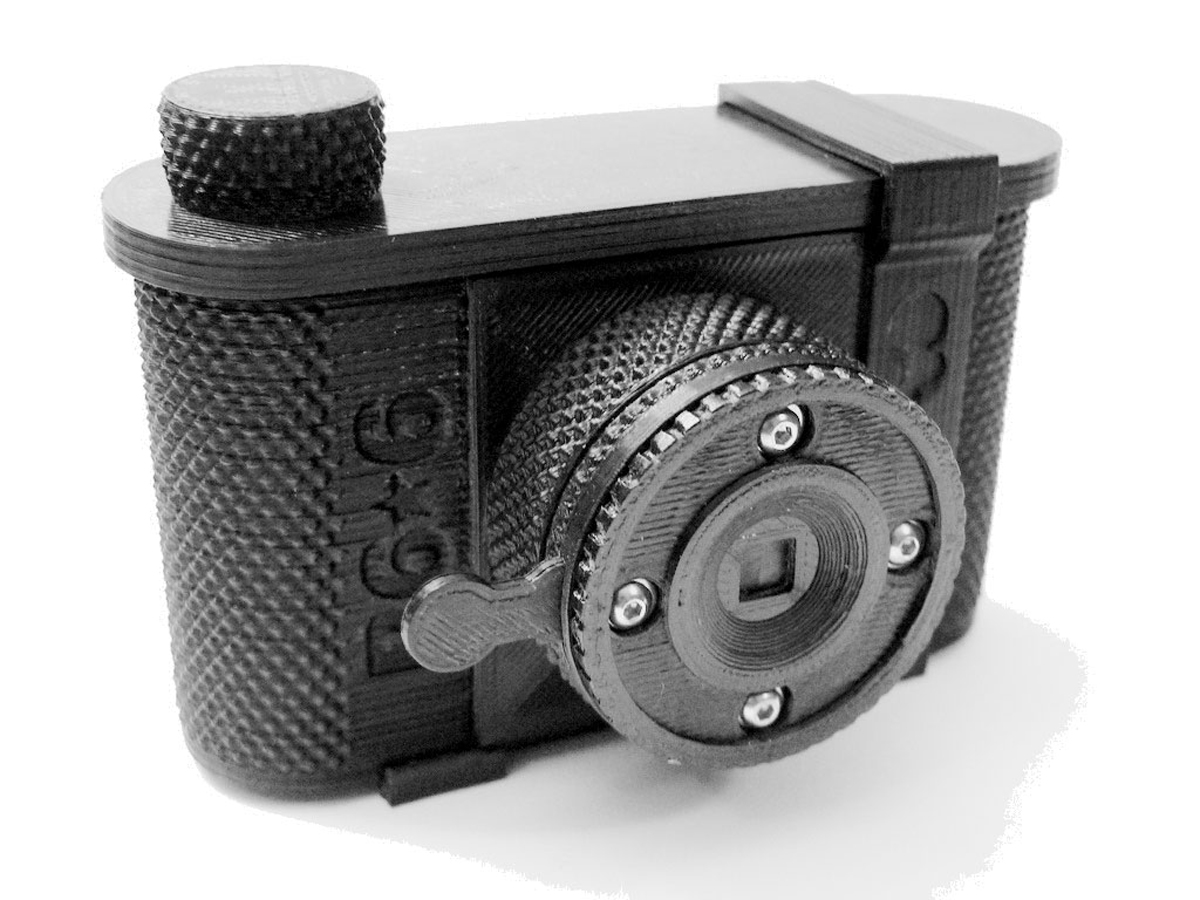
The P6*6 is a 3D-printed pinhole camera, glued and fastened together with 3mm nuts and bolts. All of the individual parts print without support and fit on a 6-inch square print bed. The files are available for download from Thingiverse.

The P6*6 comes in two focal lengths, 35mm and 50mm. It uses 120 roll film and makes an impressive 6cm square negative — roughly 4 times larger than a negative from a standard 35mm camera. 120 film is widely available and can be found at camera stores that cater to professional photographers or from internet vendors.

P6*6 Specs:

  • 120 film, 6×6 format
  • 50mm focal length:
    •  f-stop of f/167 with 0.30mm pinhole
    •  62 degree vertical and horizontal angles of view
  • 35mm focal length:
    •  f-stop of f/135 with 0.26mm pinhole
    • 77.4 degree vertical and horizontal angles of view

BONUS: Check the last step in this project for new, optional accessories you can print!

Project Steps

Print your camera parts

Download the 3D files from Thingiverse and print the camera parts:

A — Knob, used to advance the film

B — Cap, snaps onto the body

C — Baffle

D — Winder, engages the take-up spool

E — Film clip, keeps film tightly wound on the spool during unloading

F — Frame slide, allows viewing of frame number on film backing

G — Body

H/I — Body clip and leveling spacer, prints as joined pieces

J — Extension, 50 mm or 35 mm length

K — Pinhole disc, replaceable pinhole mount

L — Pinhole clamp

M — Shutter blade

N — Shutter clamp

O — Trim ring

When preparing the STL files for printing, use the following slicing settings:

  • 0.25mm layer height
  • 2 perimeters (or “shells”)
  • 3 solid layers top and bottom
  • 50% infill

Gather tools and materials

NOTE: Relax — The pinhole is not as critical as it seems. You can purchase a precisely laser-drilled pinhole on the Internet or easily make your own from brass shim stock, a soda can, pie plate, etc. (Aluminum foil is too fragile.)

Smooth and fit the printed parts

Every joint between parts in the P6*6 has a potential for photo-ruining light leaks —unintended openings that allow light into the camera. Careful attention to fit will ensure awesome photos. If necessary, use fine sandpaper or a file to smooth mating surfaces.

Carefully enlarge bolt holes with a 1/8″ drill bit.

Pay special attention to the frame surface, formed by the bottom of the extension — the film slides across this surface when winding, and it forms the margin of your photographs. Surface irregularities could scratch the film, and an unevenly trimmed inside perimeter will be preserved as an uneven border on every photograph you make. Additionally, slightly round and smooth the bevel edge of the frame to avoid scratches on the film.

Before proceeding, check the fit of all mating parts. Refer to the exploded parts diagram. All parts should fit together without distorting. The cap should fit the body securely. The shutter blade should be slightly snug between the pinhole clamp and the shutter clamp.

Glue the tripod mount

A ¼-20 nut is the standard tripod attachment. Carefully bond the flanged nut in its hexagonal hole in the body, flush with the bottom of the body, using a bit of epoxy on the inside.

Assemble the cap and winder

Parts A, B, C, and D.

The winder drive passes through the baffle and cap and into the knob. This is designed to be a friction fit. If the narrow part of the winder drive is slightly too large to fit through the baffle into the knob, enlarge the holes rather than reducing the size of the winder shaft.

Assemble the extension and pinhole/shutter

Parts J, K, pinhole, L, M, N, O, nuts, bolts, and (optional) washers. See diagrams.

Everything should fit together tightly prior to fastening. The extension, pinhole clamp, and shutter clamp must fit without interference.

Bolting all these parts together can be a bit fiddly, but it’s important to assemble them before gluing the extension and body together. A small Allen wrench is handy to position the nuts in the nut traps (in the extension) during assembly. The shutter should snap open and closed. It is easy to overtighten the bolts.

Use super glue to mount the trim ring on the face of the shutter clamp.

Add the velvet lining and red window

For best results, the inside back of the body can be lined with velvet behind the frame. The velvet provides a gentle friction that keeps the film in place and serves to reduce the effect of stray light from the frame index window. Lining the inside surface of the cap also minimizes light leaks. Download the velvet templates at thingiverse.com/thing:157844 and cut them out of self-adhesive velvet.

Cut a 15mm–18mm disc of transparent red plastic, and tack it in place in the recess inside the body with a couple tiny dabs of super glue. The hole in the middle of the adhesive-backed velvet will overlap the disc and secure it in place.

Carefully use the tip of an X-Acto blade to slide the velvet into position when attaching it to the body and cap. It must be wrinkle free.

Assemble the body/extension Joint

“Dry-fit” the extension and body before gluing them together. They’ll only fit one way — the “50” (or “35”) marking will be visible. Any interference could mean light leaks. The tripod nut must fit without difficulty. Resolve any issues before you glue.

During gluing, space the frame surface about 0.50mm away from the velvet. You can use 5 sheets of printer paper (0.10mm thick each).

IMPORTANT: There will be a gap between the extension and the body on each side when the

2 parts are properly fitted, as shown here.

Gluing

For ABS, plumbing cement works well (and comes in camera black). Work fast — the solvent evaporates quickly and the cement gets rubbery.

For bonding PLA, a dark epoxy is best, but gap-filling super glues or “Plastic Welder” type glues also give good results.

Follow the directions on the label. Too much glue will ooze out of the joint and muck up your lovely camera’s appearance. Use a C-clamp or stout rubber bands to precisely clamp the 2 parts together.

Load the film

Allow the glue to dry, then load your new camera with 120 film, and slide the body clip onto the camera.

Make some pinhole photographs!

Sample shots achieved with the pinhole camera.

Print some accessories (optional)

Hate the flat shutter plate on the front of the “lens”? Dress it up with the Trim Ring & Pinhole Cap: thingiverse.com/thing:219829

Viewfinders — You asked for ’em, I designed ’em: thingiverse.com/thing:363857

Butter Shutter for remote cable release: thingiverse.com/thing:395523

Mini P6*6 Pinhole Camera Keyring: thingiverse.com/thing:252857

Conclusion

To see more pinhole photos taken with the P6*6, visit my Flickr page at flickr.com/photos/theschlem/sets/72157645030373964.