


The XR2206 is a slightly obscure audio chip that has surprising potential. It generates triangle waves and pure sine waves, and allows you to control them in unexpectedly imaginative ways. You could use it as the heart of a sound synthesizer.
I’ve been having a lot of fun playing with the XR2206 since it was suggested to me by a reader of my books named Jeremy Frank, who acquired some basic knowledge from Make: Electronics, but now seems to know more about some topics than I do.
Frequency and Amplification
The pin functions are shown in Figure A, and a basic test schematic is in Figure B. Don’t be put off by the apparent complexity. Each section functions separately and is easy to understand.


For power, the XR2206 accepts 10VDC to 26VDC. The simplest option is to use the kind of 12V AC-to-DC adapter that you can find for less than $10 on eBay.
Pin 2 of the XR2206 is the audio output, which requires amplification. Pass it through a 33µF coupling capacitor and a 1M series resistor to the input of an LM386 single-chip amplifier, which has limited power, but is very simple. See Figure C below.

A resistor-capacitor combination sets the audio frequency — similarly to a 555 timer, but with greater simplicity. A timing capacitor goes between pins 5 and 6, and a resistance goes between pin 7 and negative ground. Acceptable capacitor values range from 0.001µF to 100µF, while resistance should be between 1K and 2M.
Frequency is calculated using a very simple formula: f = 1,000 / (R × C), where R is in kilohms and C is in microfarads. I chose a 33nF ceramic capacitor and 500K trimmer. Because I used the dual inputs on pins 7 and 8 (more about them later), the frequency is doubled, ranging from about 60Hz to 7kHz. This is close to the full audible spectrum.
The resistor network applied to pin 3 allows you to boost the output from the chip. You can ignore pins 15 and 16, which enable you to fine-tune the wave symmetry, but are not needed for our purposes. Before I explain the other pin functions, I suggest you leave inputs A, B, C, and D unconnected, put all the switches in their up positions, and get acquainted with the basic functions.
Making Music
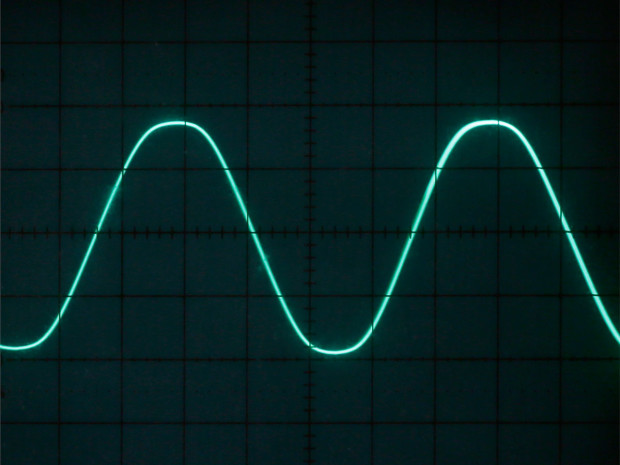
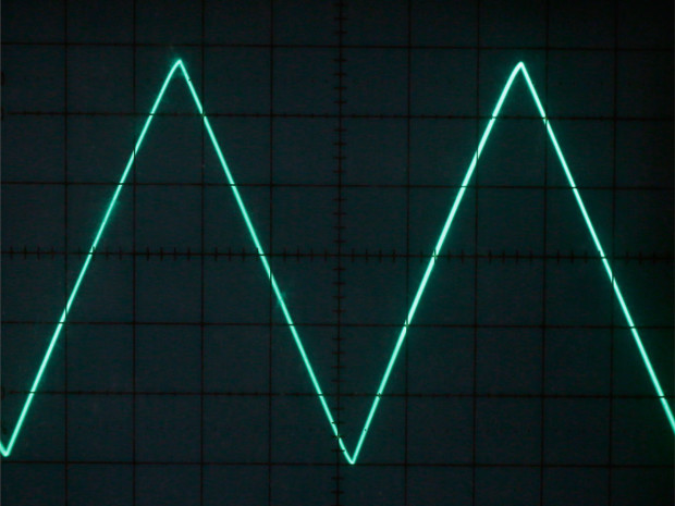
Switch 4, connecting pins 13 and 14 through a 220-ohm resistor, selects sine-wave output (Figure D) or triangle-wave output (Figure E). Sine waves have a natural quality — the kind of mellow tone you get by blowing across the top of a bottle. Adding higher frequencies to a basic sine wave can emulate various music instruments. A triangle wave (also known as saw-tooth) is richer in harmonics, and sounds more artificial.
When switch 3 is up, the XR2206 automatically uses the resistances on pin 7 for the rising time and pin 8 for the falling time of each audio cycle. This allows you to create asymmetrical sound waves. Figures F and G show some that I created. If you have an oscilloscope, you can view these signals yourself.


Now for some of the interesting features. Pin 9 is a digital input. In a logic-high state (2VDC or more) it selects the resistance attached to pin 7 to control frequency. In a logic-low state (1VDC or less) it selects the resistance attached to pin 8. If you feed a series of pulses to pin 9 — from a 555 timer, for instance — the XR2206 will flip between two different frequencies (Figure H). If you do this very quickly, unique sounds are possible.

Because a 555 tends to create voltage spikes, I used an Intersil 7555, which has the same pin functions but a cleaner signal. If you’ve read Make: Electronics, the circuit shown in Figure I will look familiar as a basic frequency generator, with some additions. The 100µF capacitor stops frequencies from the XR2206 from trespassing into the 7555. The SPDT switch selects either a 4.7nF capacitor to generate low frequencies ranging from 150Hz to 10kHz, or a 1µF capacitor for 1Hz to 60Hz. The SPST switch rounds the square-wave output with a 1µF bypass capacitor.

The complete breadboarded circuit is shown in Figure J, with component values in Figure K. I used E-switch EG1218 SPDT slide switches, because they take up minimal space and are very affordable.


Use any combination of switches 1, 3, 4, and 5 to apply the 7555 output to the various inputs of the XR2206 (Figures L and M). Run the 7555 slowly, and it can pulse the sound or create a tremolo or vibrato effect if you apply it to pin 1, which modulates the amplitude of the sound (Figure N).


Going Further
If you want to go further, substitute another XR2206 for the 7555 timer, so that your control pulses will have more subtlety than a simple square wave.
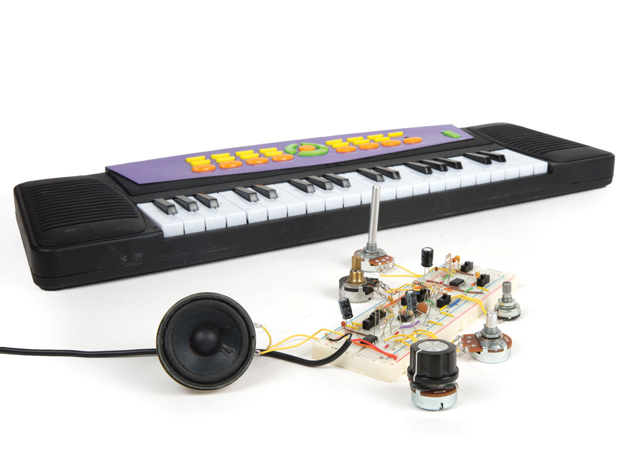
To create a real keyboard-controlled synthesizer, buy the cheapest old keyboard you can find, open it up, and look for the contacts that close when keys are pressed. Each key must apply a different resistance to pin 7 of the XR2206, to generate a different note. You’ll need as many trimmers as there are keys, and to adjust the trimmers you can use an electronic guitar tuner.


Lastly, here’s a fun experiment. You can run the XR2206 at a radio frequency, such as 70kHz, using a 0.001µF timing capacitor and a 1K resistor in series with a 5K trimmer between pin 7 and negative ground. (Leave pins 8 and 9 unconnected.) Pass the signal from a microphone through an LM358 op-amp into pin 1, which enables amplitude modulation. When my friend Jeremy Frank did this, he managed to convert the oscillator chip into a tiny radio transmitter.
What other interesting things are possible? Your first step should be to read the datasheet for the XR2206, which is very informative. I have a feeling we’ve only just scratched the surface with this versatile audio generator.


