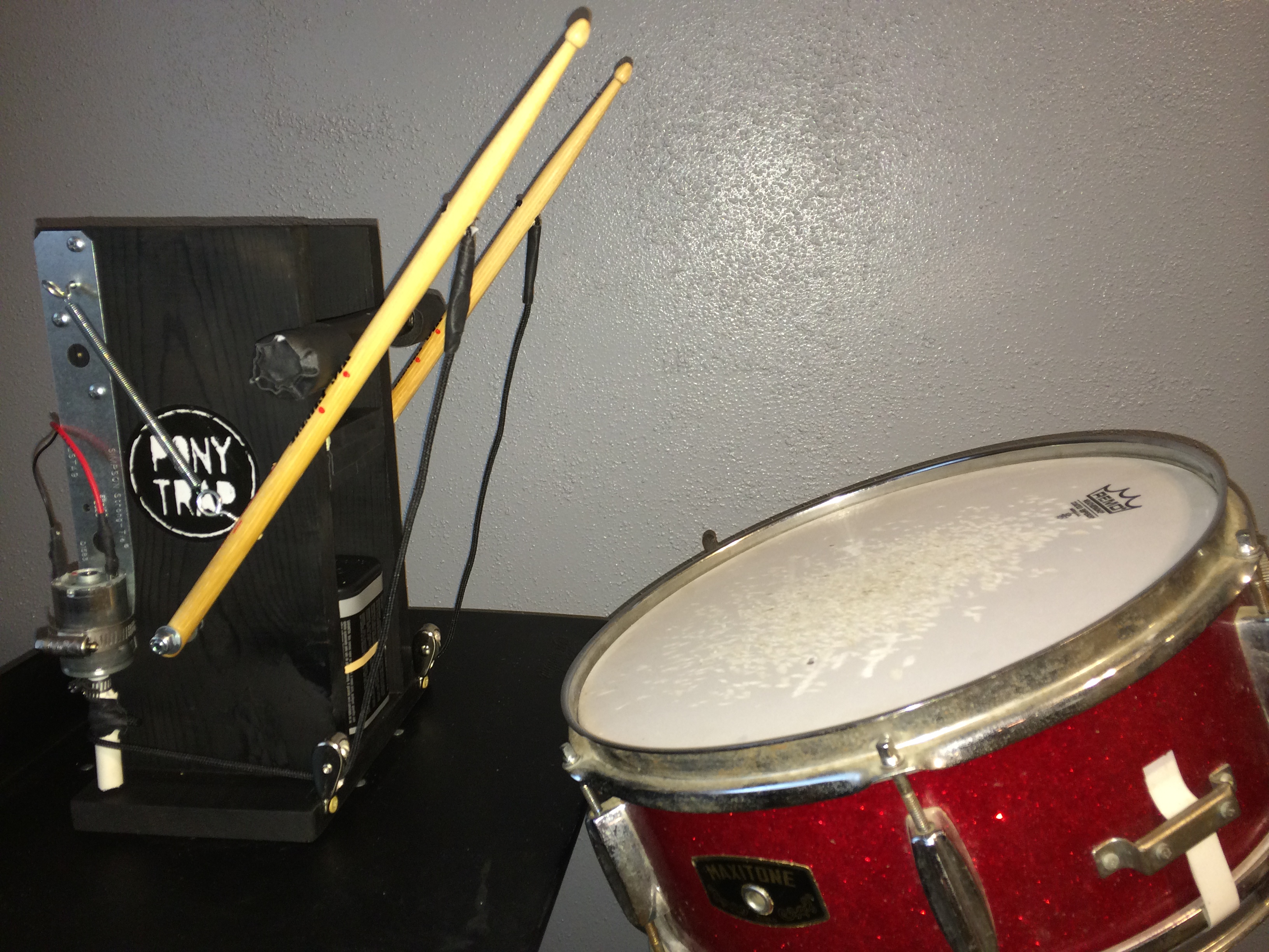
Photo by Hep Svadja
Photo by Hep Svadja

Everyone has a Maker in them. We make for fun and exploration, we make to test ideas, and we make to solve real-world problems. Ponytrap wasn’t intended to be a Maker band — we just seemed to have a difficult time finding a drummer that wanted to play the classically-inspired tribal rhythm industrial music that we wanted to do. In retrospect, maybe that’s not a surprise, but at one point a couple of years ago, Quentin found himself stuck in the middle of a seemingly endless free-form jazz odyssey, and the idea to build his own drummer just kind of materialized. After several evolutions, dozens of burned out motors, and a lot of trial and error, Ponytrap has a solid drumline made entirely of robots.

Photo by Hilary Thomas-Oliver
YouTube player

Our construction ethos is hand tools and off-the-shelf parts. Nothing about our machines needs to be custom built or ordered from a specialty warehouse. So, we wanted this project to work on the same principals. You can obtain everything in the parts list from a retail store and build the entire thing with the simple toolkit pictured in the first step. At the end of the day, you’ll have an Arduino controlled drumming robot that can play complex beats and will always show up to rehearsal.

After we’ve finished building the drum robot, you can find the software to create a version of this beat for your machine in Appendix B.

YouTube player

The Concept

For Ponytrap’s machines, a big part of our aesthetic was to make the drum both physically and visually satisfying. It may be more simple to use smaller, faster actuators, but we really like to see, hear, and feel the drums beating away! Our big machines are fun to watch and they pound as hard as a human drummer. The smaller version for this project hits solidly and has a great visual as well.

The finished robot ready to play.

This drumming robot consists of two drumsticks controlled by an Arduino, and all of the beats will be written directly into the software of the Arduino. The drivetrain operating the drumsticks functions by turning a spindle/driveshaft which pulls a string that draws the drumstick down to the surface for a strike. After the strike, a return spring will draw the drumstick up while unwinding the spindle to be ready for another strike. The motors are turned on and off by the Arduino via TIP120 transistors and powered by 6-volt lantern batteries wired in series to 12-volts. For our demonstration, we used a snare drum that we had on hand, but any drum is suitable; if you do not have drums handy, plastic buckets make excellent substitutes.

austin

Ponytrap brought their drumming robot to the Austin Mini Maker Faire. Learn more about it here!

What will the next generation of Make: look like? We’re inviting you to shape the future by investing in Make:. By becoming an investor, you help decide what’s next. The future of Make: is in your hands. Learn More.

Project Steps

Parts and Tools

All of the required parts (48” of 1×6 lumber not pictured) are shown above and listed on the right.

The required tools are shown in the second image and also listed on the right. This entire project can be completed with this minimal toolkit.

Prepare the Parts

The first image shows the prepared parts cut, marked, and pre-drilled. Note the placement of the Simpson Strong-Tie for use as a jig to mark the top four small holes.

Trim one of the four tabs from the PVC driveshaft.

Preparing Lumber and PVC

Cut the the 1×6 lumber into pieces of 8” (the base), 3½” (the shelf) and two 12” pieces (the sides).

Cut the ¼” PVC into two 2½” pieces. These pieces will connect to the motors and be referred to as “driveshafts.”

Cut four vertical slots ½” deep into one end of each driveshaft. If you have tin-snips, heavy duty scissors, or wire cutters, they will work just as well or better than the saw for this step.

Bend and cut one of the “tabs” from each driveshaft. Depending on the size of the pinion gears on your motors, this may not be strictly necessary, but we’ve found that this step makes mounting the driveshafts to the motors a bit more secure. Wire cutters or heavy duty scissors are ideal for this task, but careful use of the saw will also get the job done.

Cut the ½” PVC into one 8” piece. This piece will server as the stop/resting place for the drumsticks and will be referred to as the “bumper”. We used ½” PVC mainly for ease of mounting, but excess ¼” PVC can be substituted for this part.

If you have sandpaper or files, this is a good time to smooth and square the edges of the PVC and the cut lumber.

Prepare Drumsticks

Drill a ¼” hole through each driveshaft at 1” from the slotted end. If available, use sandpaper or file to clean up the edges of the hole.

Drill a ¼” hole through each drumstick ½” from the non-tip end. This hole is for the axle. For best presentation, drill this hole so that the label of the drumstick faces up when placed on the axle. We’ll call the label side the “top” of the stick for future reference.

Drill a ¼” hole through each drumstick 4” from the tip end. This hole is for the shoestring/pull-cable and should be on a perpendicular axis from the axle hole — i.e., through the top.

Drill a ¼” hole through both of the 12” pieces of 1×6 lumber. The hole should be located 3½” from one of the short sides (this will be the base of the box we’re building) and 2¾” from the long sides (center it, a standard 1×6 is actually 5½” wide). These holes will be for the axles of our drumsticks. Make sure they are nicely round and smooth.

More Work With the Lumber

Use a pencil to label each edge of each of the 12” pieces of lumber. Write the word “Base” along the short edge nearest the ¼” hole that we just drilled. Write the word “Top” along the opposite short edge. Along one long edge, write “Back” and write “Front” along the opposite long edge.

Use a pencil to mark the 8” piece of lumber (this will be the base of our box). Mark the side you wish to face up as “Top” and choose one of the long edges to mark as “Front”.

Use a pencil to mark the 3½” piece of lumber (this will be the shelf for our Arduino and breadboard). Mark the side you wish to face up as “Top” and chose one of the short edges to mark as “Back”.

Use one Simpson Strong-Tie to mark pilot holes on each 12” piece of lumber. The Strong-Tie should be flush to the top, with the long edge flush to the back. See photo in step 7 to check placement.Mark each of the four small holes nearest the top. Repeat this process in mirror on the other 12” piece of lumber (so that the marks all face “outside” when the two pieces are assembled as the sides of our box).

Finish Preparing the Parts

Using the 3/32” bit, we’ll pre-drill several pilot holes for our screws. (All of the pilot holes should go through the piece when drilling from a face. The holes that are drilled into edges should go as deep as possible. Take care to make each hole as straight and true as possible.)

  • Drill each of the 4 holes previously marked on each 12” piece of lumber. These holes will be for mounting our Strong-Ties and our return spring eyelet.
  • Drill a hole 5” from the top and 1½” from the back of each 12” piece of lumber. These holes will be for mounting our shelf.
  • Drill a hole 5” from the top and 1½” from the front of each 12” piece of lumber. These holes will also be for mounting our shelf.
  • Drill a hole 2” from the top and centered in the front edge of each 12” piece of lumber. These holes will be for mounting our bumper to the face/front of our box.
  • Drill four holes in the bottom of the 8” piece of lumber. Each hole should be 1¾” from a short edge and 1½” from a long edge. These holes will be for mounting the 12” sides to our 8” base.
  • Drill two holes in the 8” piece of lumber. Each hole should be in the edge marked “Front” and located ¼” from the top and 1” from the outer edge. These holes will be for mounting our pulleys.
  • Use the Arduino as a guide to mark the four mounting holes into the 3½” piece of lumber. These holes will be used to mount the Arduino to the shelf. Only two mounting screws will be necessary, but we will pre-drill all four holes. Make sure to mark the holes so that the Arduino sits on the side marked “Top” and the serial port is flush to the edge marked “Back” of the shelf.
  • Drill two holes through the Bumper — one each at 1¾” inches from each end.
  • Drill a hole in the “top” (label side) of each drumstick, 3½” from the non-tip/axle end. This hole will be for mounting a spring retaining eyelet and should face up when the stick is placed on the axle.

At this point, all of our materials should be prepped for construction. Next, we’ll
assemble the body of the robot.

Build a Box

Now, we will assemble the box/frame that will form the body of our drumming robot and contain all of our components. If there are any questions about the alignment of the parts, please refer to the photograph.

Align one of the 12” sides to the pre-drilled holes in the top of the 8” base. Make sure that all edges marked “Front” are on the same side. Turn the pieces upside down and screw together from the bottom of the base; use the 1½” deck screws. Make sure that the screw heads are flush or countersunk so that the unit will not wobble when turned upright. Do the same for the other 12” side.

Align the 3½” shelf to the pre-drilled shelf holes (5” from top and 1½” from front and back) and between the two sides. Using 1½” deck screws, screw the shelf in from both sides. Make sure the screws go in straight and do not poke up through the top or bottom of the shelf. This step may be easier with the box laying down on its side.

If you care to paint the unit, this would be the time to do so. We went with classic black, but shiny silver is also a good robot choice. Now would also be the time to apply any decals or pinstriping. Wait until paint is dry before continuing to the next step.

Align the pre-drilled holes in the bumper to the holes in the front edges of the sides (2” from the top) and attach the bumper with 1½” deck screws. Make sure the screws go in straight and do not poke out through the sides.

To reduce the noise of the sticks hitting the bumper, we can add some padding to the ends of the bumper. We wrapped a scrap piece of pipe insulation using the duct tape; a folded up piece of paper towel would also work well for this function.

Using 1½” deck screws, secure the pulleys to the pre-drilled holes in the front of the base (1” from the outside edges). The pulleys should be firmly secured to the base and not left loose. (See photo for proper alignment.)

The body of our robot is now complete. In the next step, we’ll build out its moving parts.

Start Building the Drivetrain

It is time to finish building the machine by assembling and mounting the drivetrain including the motors, driveshafts, and drumsticks. Each element of this step is important to the function of the robot. Make sure that every piece moves freely before moving on to the next element. We will wait to install the pull-strings until after we have tested the Arduino control of the motors in a later step.

To work on this part of the project, you will need two motors. As noted in the parts list, we used the Mabuchi RS-545SH for this project. When we first began building these machines, we salvaged motors from used, rechargeable power drills and found that they worked the best. If you’re going that route, try to find 12-volt drills to match the power source we’re using here. It works best if the motors are from the same manufacturer and have the same specifications. Whatever motor used will need to have a pinion gear for attaching the driveshaft.

Working With the Motors

Place a small hose clamp over the slotted end of a driveshaft. Make sure the edges of the hose clamp and driveshaft are flush. Use a screwdriver to tighten the hose clamp lightly until it just barely begins to close the tabs. Insert the motor’s pinion gear into the slotted end of the driveshaft and tighten the hose clamp until the driveshaft is secure. The hose clamp needs to be tight enough to prevent the driveshaft from coming loose, but be wary of over tightening to the point of stripping the hose clamp. Make sure that there is minimal clearance between the driveshaft and the body of the motor, however, there must be just enough clearance that the shaft spins freely without rubbing the body of the motor. Also make sure that the shaft spins true and centered with minimal wobble. This step is extremely important to the function of the robot and may need to be repeated until correct. Repeat this process for the second motor and driveshaft.

Using a large hose clamp, mount the motor to one end of a Simpson Strong-Tie. Align the edge of the body of the motor with the end of the Strong-Tie. Make sure that the driveshaft and its hose clamp are free and clear of the Strong-Tie so that the driveshaft spins freely. Also place the motor’s power tabs (opposite end from the pinion gear, the two tabs we will connect the wiring to) so that there is maximum distance from each tab to the metal Strong-Tie. Make sure that the holes in the opposite end of the Strong-Tie match the pre-drilled holes on the side of the wood box and that the tightening screw of the large hose clamp will be on the outside of the assembly to enable adjustment of the motor’s position. Refer to the photos in steps nine, ten and eleven to ensure proper placement. Tighten the large hose clamp until the motor is secure – the Strong-Tie will bend slightly to the contour of the motor. Repeat this process for the other motor and Strong-Tie.

Using three #8 screws, attach the Strong-Tie with motor to the side of the box. Place the screws as shown in the photo. The second pre-drilled hole from the top will remain empty. Repeat this process for the other Strong-Tie and motor.

Finishing the Drivetrain

Make sure there is minimal clearance between the end of the motor’s driveshaft and the base of the box. The end of the shaft should be as close to the base as possible while still spinning freely. Loosen the large hose clamp slightly to adjust the height of the motor up or down to achieve the best clearance, then re-tighten the hose clamp securely.

Use pliers to bend each of the four eyelets sideways so that there is a slight opening. Compress the eyelets so that the open end slightly overlaps the screw end – there should remain enough of a gap so that the loop end of a spring can pass easily into the eyelet (see photo in step 8).

Screw an eyelet into the remaining pre-drilled hole of the four small holes in the top end of the Strong-Tie. Repeat for the other side.

Screw an eyelet into the top of each drumstick in the pre-drilled hole 3½” from the axle end.

From inside the box, insert a 2” long hex-head ¼” bolt through the ¼” hole drilled in the side. The bolt’s head should be inside the box with the threaded end sticking out. Place a locking washer around the bolt and tighten the bolt solidly with a locking wax nuts. Repeat for the other side.

Place a regular washer on the bolt on top of the locking nut and then install a drumstick on the bolt. The drumstick’s eyelet should be on top and the drumstick should be placed so that the tip points toward the front of the box. Make sure that the stick rests below the bumper and is not trapped above and behind the bumper. Also make sure that the stick travels freely and smoothly on the bolt. If the motion is not smooth, use sandpaper, a file, or a drill bit to clean up the axle hole in the drumstick. Place another regular washer on the bolt outside of the drumstick. Secure the assembly with a second locking wax nut; tighten the nut only so far as to make sure that the drumstick does not wobble, but can still move freely and easily. Slip one end of a return spring into the eyelet of the drumstick. Pull the drumstick up to the bumper and slip the other end of the return spring into the eyelet mounted on the box. Repeat for the other side.

If you have graphite, lubricate the axles as well as the pulleys to assure smooth, noiseless function.

Our robot is almost ready to make some noise! Now we’ll move on to assemble the circuit that makes the robot’s brain.

Start Building the Circuit

In this step we will build the circuit. A basic understanding of how the circuit works is helpful to understand the assembly steps. The circuit functions like this:

  • The software on the Arduino switches one of its “pins” to HIGH allowing power to flow to a transistor.
  • The activated transistor allows power to flow from the lantern batteries to a motor.
  • The motor turns and pulls a drumstick down for a strike.
  • When the Arduino’s software switches off its pin, the transistor breaks the circuit between the lantern batteries and the motor.
  • The motor stops running and the return spring pulls the stick back up to resting position.

A detailed understanding of the TIP120 transistor we will use is beyond our scope, but there are many excellent online resources if you care to search the name and dig into the details. We will need to know some basic terminology however. The TIP120 has three metal prongs called legs. With the transistor facing you, from left to right the legs are called: base, collector, and emitter.

We will also use a solderless breadboard which will allow us to make simple push-in connections for our circuit. If you are unfamiliar with breadboards, search for “breadboard tutorial.” There are many excellent resources to read.

This would also be a good time to familiarize yourself with the Arduino if you are not already. Search for “Arduino Playground” and you will find a wealth of code examples, tutorials, and explanations of the board’s layout. Even though we will not be writing code to the Arduino in this step, we will be connecting to it, so an understanding of the unit is helpful.

If you are using an Arduino to which you’ve previously uploaded software, make sure that any code that switches power to the output pins is removed or commented out before connecting the Arduino into the circuit! If not, there is a risk that the motors will activate when the Arduino is powered up later.

Continue Building the Circuit

Begin by inserting two TIP120 transistors into the breadboard; each leg should be in a separate numbered row. [For visual ease, we placed the transistors so that the center leg (the collector) is on a row with a visible number, in this case, numbers 10 and 20. We’ll proceed by using those numbers in the descriptions, but you may use any rows that suit you, so long as the connections are correct.]

Cut two short pieces of 22 gauge solid core hookup wire (black is the appropriate color if available) and strip short sections of insulation from each end.

Insert the hookup wire into the breadboard so that the right leg (the emitter) of the transistor (in row #9 for our example) is connected to the long blue/negative rail on the outside of the breadboard. Do the same for the other transistor (row #19 in our example).

Take two N4004 diodes and trim their legs to approximately ½” and bend the legs downward.

Make sure that the end of the diode with the silver band is pointing toward the transistor and insert the legs of the diode into the breadboard so that the transistor’s middle leg (the collector, row #10) connects to the long blue/negative rail. It is very important that the silver band faces the transistor! This diode prevents the motor from sending electricity backwards through the circuit and harming the transistor. Do the same for the other transistor (row #20 in our example). Follow along with the photos to make sure everything looks correct so far.

At this point, it makes sense to install the breadboard and Arduino onto the robot body’s shelf. This will make the working space a little tight, but allows us to trim our wiring to length. If you find that it is too inconvenient to work in the narrow space, you may install the breadboard and Arduino at the end of this section. Our breadboard came with two-sided tape on the bottom and we simply stuck it to the front of the shelf and used our black tape to tidy up the look. Install the Arduino with two short ⅛” or smaller screws into the pre-drilled holes at the back of the shelf. Do not over tighten the screws as they can crack the Arduino’s body. Refer to the photo for proper placement.

Use tape or a heavy rubber band to secure two 6-volt lantern batteries side by side.

Cut a short piece of hookup wire and use it to connect the positive terminal of one battery to the negative terminal of the other battery.

NOTE: Be sure that the terminals are on separate batteries! If you accidentally connect the terminals of the same battery, this will create a short circuit and a risk of fire!

Strip the ends off the hookup wire, wind one end around each terminal, and tape it off to prevent accidental short circuits. We used a testing wire with clamps for this step, but the hookup wire will work perfectly well. This step has the effect of wiring the two batteries in series and turning the two 6-volt batteries into a single 12-volt unit. Going forward, we will refer to this unit as a single battery with the positive and negative poles being the poles that are not connected to anything at this time.

Place the battery in the body of the robot in the space below the shelf. Wiring will be easiest if the negative terminal is toward the front. If you wish, you can secure the battery in place with heavy tape.

Finish Building the Circuit

Cut a piece of hookup wire (black is preferable) long enough to reach from the battery’s negative pole to the breadboard’s long blue/negative rail. Strip the ends and connect the negative pole to the breadboard’s rail. Make sure this is the same rail to which the diodes are connected.

Cut a piece of hookup wire (black is preferable) long enough to reach from one of the Arduino’s ground pins (marked “GND”) to the breadboard’s negative rail. Strip the wire’s ends and make this connection; be sure it is the same rail to which all other connections have been made.

Cut a piece of hookup wire (red is preferable) long enough to reach from the Arduino’s output pin #7 to a transistor’s left (base) leg (row #21 in our example). Strip the wire ends and make this connection. You may use any of the output pins you desire, but make sure to use the same numbers in the software later. Repeat this step from another Arduino pin to the other transistor (pin #8 to breadboard row #11 in our example).

Cut a piece of hookup wire (we used black although green or yellow is preferable) long enough to reach from a transistor’s center (collector) leg to the farthest terminal of a motor. (All wires to the motors must be long enough to reach either terminal.) Strip both ends of the wire. On one end, crimp on a female wire connector and secure with tape or heat shrink; connect this end to the motor and connect the other end to the collector leg (row #20 in our example) on the breadboard. The connection to the breadboard should be between the diode and the collector leg of the transistor. Repeat this step from the other collector leg (row #10 in our example) to the other motor.

Cut a piece of hookup wire (we used red although green or yellow is preferable) long enough to reach from the battery’s positive terminal to the farthest terminal of a motor. (All wires to the motors must be long enough to reach either terminal.) Strip both ends of the wire. On one end crimp on a female wire connector and secure with tape or heat shrink; connect this end to the motor and connect the other end to the positive terminal of the battery. Make sure the battery connection is secure and unlikely to come loose. Repeat this step from the positive terminal to the other motor. Here is a case where we went a step further in our example: we used stranded wire (for a little more flexibility) and tied the battery ends together into a metal clip. This allows us an easy and stable battery connection and will serve as a convenient way to disconnect power when needed.

Now the robot should be powered up and ready to spin the motors! Please double-check to make sure the wiring looks functionally similar to the photos – in the next step, we’ll load up some software and start making noise!

Test Drivetrain

It’s time to write some basic software for the Arduino and test to make sure that the motors are running correctly. Then, we will connect the pull-strings for the drumsticks and determine how to make them strike most effectively.

Before we begin, note that connecting the Arduino to a computer via a USB cable will power up the Arduino. If there is running software that activates the Arduino’s output pins, the motors may engage. We suggest disconnecting the motors (simply pull the wire connectors off the terminals) until you are certain that they will not power up accidentally from the software. Also remember that the way to power down the Arduino is to unplug the USB. If you are not familiar with the basic workings of the Arduino, please go to Arduino Playground and learn the basics of its software and functionality.

Test Drivetrain: Basic Software

Make sure the area around the motors is clear, connect the Arduino to your computer via USB, and upload this software:

int striketime = 100; // the length of time the motor will be on
int resttime = 2000; // the length of rest between strikes

void setup() {

pinMode(7, OUTPUT); // set the output pins

pinMode(8, OUTPUT); // make sure these pin numbers match your wiring

}
void loop() {

digitalWrite(7, HIGH); // turn on motor 1

delay(striketime);

digitalWrite(7, LOW); // turn off motor 1

delay(resttime); // wait

digitalWrite(8, HIGH); // turn on motor 2

delay(striketime);

digitalWrite(8, LOW); // turn off motor 2

delay(resttime); // wait

}

In this code, “striketime” is the length of time in milliseconds that the motor spins. Pins #7 and #8 (or whatever pins you have chosen) are designated as OUTPUT pins. When we set one to HIGH, its motor should spin. When we set it to LOW, its motor should turn off. If all is going well, each motor should spin for 100 milliseconds, turn off, and two full seconds (“resttime” = 2000 milliseconds) should elapse before the other motor spins. This happens in a loop and will continue until you power down the motors or the Arduino.

If the motors are not operating as expected: double-check all of your connections, make sure the Arduino pin numbers in your software match the ones you’ve connected, make sure the motors are functional and can operate on the amount of power supplied by our battery, make sure the driveshafts are not binding against the motor housing or the body of the robot.

Test Drivetrain: Connect Driveshafts

Once the motors are operating properly, it’s time to connect the driveshafts to the drumsticks. First, power down the Arduino. Thread a boot lace (the smoother and rounder the better; flat sneaker laces or leather laces are not suited to this task) through the ¼” hole in the drumstick near the tip and tie it off. You can see in the photos that we doubled the lace and held it together with tape, but a simple knot will also work fine. Thread the other end of the lace through the lower opening of the pulley and then on to the 1/4” hole in the driveshaft. Pull the lace through the hole in the driveshaft until not quite taught; a little slack allows the motor a moment of free spin at start-up and greatly reduces stress. Beware of too much slack as this simply creates a longer run for the motor. Tie a knot in the shoestring around the driveshaft. Try to keep the knot tight and close so that it will minimize any rubbing against to body of the robot. Cut off any excess string from either end. Use a piece of strong tape to cover the knot – this will help prevent binding and extra noise associated with rubbing. (Please refer photos in steps eight and nine if there are any questions about placement of the pull-strings.) Test the motion of the stick by hand winding the driveshaft to see that it has a good even pull to the drum/strike surface. The return spring should lift the stick and unwind the shaft when you release. Ideally, the return spring should be as lax as possible while still fully raising the stick to the bumper and unwinding the spindle. If the spring seems too resistant or too loose, the tension can be adjusted by moving the location of the eyelets on the drumstick, the body, or both. If the springs and sticks are identical to those in the parts list, the given locations of eyelets should work well.
Repeat this process for the other stick and pull-string.

Make sure that the tips of the sticks are aimed at your drum / strike surface and that the area is clear from obstructions. Plug in the USB and power up the Arduino. The sticks should be alternately striking toward the drum every two seconds. Do not be concerned if the sticks do not quite reach the drum or if they strike too long and stall. Our next job is to adjust the strike time for a quality hit.

The primary way to change the quality of the strike is to modify the “striketime” variable in the software. We started with 100 milliseconds because that’s what works best with our machine. However, subtle differences in parts, construction, drums, and placement can all have an effect on the strike of the sticks. If the strike is not strong enough try raising the “striketime” by small increments until the sticks hit the way you’d like. If the “striketime” is too long, the motors will stall (although the sticks will likely bounce upward, you may notice a hitch in their return). This causes unnecessary wear on the motor and may cause unevenly timed returns which will lead to uneven beats. In this case, decrease the “striketime” by small increments until you’ve reached a good balance. Be aware that a shorter “striketime” results in the ability to compose faster beats, so this job is crucial to finding the balance of quality and speed.

You can also physically adjust the strength and speed of the strike by raising, lowering, or tilting the drum, or by adjusting the spring tension as discussed above.

If you find that the sticks are striking unevenly, first check the axles and bolts and spring placements to make sure that they are the same. You can also switch the operating direction of one or both motors to help ensure even strikes. Make sure the Arduino is powered down and simply switch the terminal wires on the motor you wish to redirect. DC motors can spin either direction depending on which way the current flows. This is why we cut all the motor’s wires to fit to either terminal. Experiment with all four combinations of motor direction to find the setup that strikes most evenly for your machine.

Once you have a set-up that you like, make note of the “striketime” and the specific placements of the drum and robot.

Huzzah! Now we’ve got a drum playing robot! All that we have left to do is write some beats for it to perform. Let’s write some music.

Composing Beats

We’ll now talk about how to compose some beats for your new robot friend. For the purpose of this discussion, we’ll use “striketime” = 100. This will make the math easy to present; if the “striketime” you ended up with in the previous step is different, please adjust your calculations to suit. Also note that all time is represented in milliseconds, ie, 1000 = 1 second.

An important concept to understand for this way of writing beats is the difference between “striketime” and the length of a note. The “striketime” variable simply tells us the amount of time the machine requires to get the drumstick to the drum. The note length tells us the entire amount of time between each strike. For example, if we wanted a beat to happen exactly every two seconds, we wouldn’t adjust the “striketime” to 2000. This would stall the motors and not allow the sticks to return to the bumper. Instead, we will have the motors strike a consistent length of time and add resting time in between to achieve the proper note lengths. We’ll do this by using the “delay” command. Notice in the software we’ve loaded that there is a delay using the variable “resttime” of 2000 milliseconds. However, if you set a timer (or a metronome!) you’ll notice that the beats take longer than two seconds. That’s because the “striketime” adds to the total, meaning that each beat is actually 2.1 seconds long. To make a beat exactly two seconds long, we need to subtract the “striketime” (100 milliseconds in our example) from the delay. If you change “resttime” in our original sample to 1900, you will find that your beats should fall precisely in two second intervals. (As always, adjust the math to the “striketime” setting that you determined best for your set-up.)

Every beat will have both a “striketime” and a delay. So, once you’ve determined how long you want each beat to be, simply subtract the “striketime” from the desired beat length and the result will be the delay needed. Each individual beat should look something like this:

digitalWrite(7, HIGH);

delay(striketime);

digitalWrite(7, LOW);

delay(beatlength);


Where “beatlength” is total beat length minus “striketime”.

Let's Write Some Music!

To begin, we need to activate our output pins (The Arduino’s basic software structure requires a “setup” which runs once after upload or reset, and a “loop” which runs continuously thereafter:

void setup() {

pinMode(7, OUTPUT); // set the output pins

pinMode(8, OUTPUT); // make sure these pin numbers match your wiring

}
void loop() {
}

Above the “setup”, we’ll need to declare the variables we’re going to use. For this exercise, we’ll use three beat lengths; the main beat, we’ll just call “beat”, then we’ll have “fastbeat”s and “slowbeat”s. We’ll also need “striketime”.


// change this to match your striketime
int striketime = 100; // the length of time the motor will be on

// will hold the delay times for various beats
int fastbeat = 0;
int beat = 0;
int slowbeat = 0;

Finally, within “setup”, we’ll need to set values for our note lengths; be aware that longer delay times = slower beats. Once we decide how long each note should be, we need to subtract the striketime from that so we have the proper length of time for the delay command. Make sure every note length is greater or equal to striketime – it is perfectly fine for delay times to be zero, but negative numbers will yield poor results!


// set the delay times
fastbeat = 150 - striketime;
beat = 300 - striketime;
slowbeat = 600 – striketime;

Now your code should look like this:


// change this value to match your striketime
int striketime = 100; // the length of time the motor will be on

// will hold the delay times for various beats
int fastbeat = 0;
int beat = 0;
int slowbeat = 0;

void setup() {

pinMode(7, OUTPUT); // set the output pins

pinMode(8, OUTPUT); // make sure these pin

numbers match your wiring

// set the delay times

fastbeat = 150 - striketime;

beat = 300 - striketime;

slowbeat = 600 - striketime;

}

void loop() {

}

Compose Your Music

All that is left to do is to compose a piece of music. If we have a short tune that we want to repeat as a loop, we should put that code in “loop”. For our example, we’ll build a short, repeating rhythm in “loop”. But, if you want to write a longer piece that runs only once, that code could be placed in “setup,” then you could use the Arduino’s reset button, or reboot it manually with the USB cable, to start the piece again.

Let’s get a feel for the pulse of the beat length we’ve created. Put this simple beat into the “loop” section of the code and upload it. (Make sure this code is between the {} brackets of “loop”.)


digitalWrite(7, HIGH);
delay(striketime);
digitalWrite(7, LOW);
delay(beat);
digitalWrite(8, HIGH);
delay(striketime);
digitalWrite(8, LOW);
delay(beat);

We should have a nice even metronomic pulse going. As much as possible, try to spread the load by alternating which stick strikes the drum. This will give the motors a chance to stay cool and the sticks a chance to fully reset.

Add Quick Beats

Now, let’s add some quick beats to the mix and get more of a rhythm going. Replace everything inside the “loop” with this;


digitalWrite(7, HIGH);
delay(striketime);
digitalWrite(7, LOW);
delay(fastbeat);
digitalWrite(8, HIGH);
delay(striketime);
digitalWrite(8, LOW);
delay(fastbeat);
digitalWrite(7, HIGH);
delay(striketime);
digitalWrite(7, LOW);
delay(beat);

digitalWrite(8, HIGH);
delay(striketime);
digitalWrite(8, LOW);
delay(fastbeat);
digitalWrite(7, HIGH);
delay(striketime);
digitalWrite(7, LOW);
delay(fastbeat);
digitalWrite(8, HIGH);
delay(striketime);
digitalWrite(8, LOW);
delay(beat);

Now our rhythmic pattern should be “fast-fast long fast-fast-long” and will maybe start to sound a little familiar.

Finally, Let’s repeat the “fast-fast-long” pattern one more time and add another regular beat. We’ll put a slow beat at the end to finish the rhythm and give us a little break at the end of the loop. Add this code after what you already have in “loop”;


digitalWrite(7, HIGH);
delay(striketime);
digitalWrite(7, LOW);
delay(fastbeat);
digitalWrite(8, HIGH);
delay(striketime);
digitalWrite(8, LOW);
delay(fastbeat);
digitalWrite(7, HIGH);
delay(striketime);
digitalWrite(7, LOW);
delay(beat);

digitalWrite(8, HIGH);
delay(striketime);
digitalWrite(8, LOW);
delay(beat);
digitalWrite(7, HIGH);
delay(striketime);
digitalWrite(7, LOW);
delay(slowbeat);

Now we should have a pretty recognizable version of the “William Tell Overture” going!

Video of the robot playing the demo beat!

YouTube player

The full version of this code can be copied from Appendix A.

You can stop the beat by unplugging the USB cable to power down the Arduino. (Also remember to disconnect the power from the motors when you are finished using the robot; this can be done by pulling the connections from the motors or the battery.)

Try recombining the fast, regular, and slow beats to create your own rhythms; once you get good at that, try making even more kinds of beats to work with. From this point it’s open to creativity.
Have Fun!

Appendix A: Sample Beat - “William Tell Overture”

// change this value to match your striketime
int striketime = 100; // the length of time the motor will be on

// will hold the delay times for various beats
int fastbeat = 0;
int beat = 0;
int slowbeat = 0;

// Software by Ponytrap / Quentin and Hilary Thomas-Oliver

void setup() {

pinMode(7, OUTPUT); // set the output pins

pinMode(8, OUTPUT); // make sure these pin numbers match your wiring

// set the delay times

fastbeat = 150 - striketime;

beat = 300 - striketime;

slowbeat = 600 - striketime;

}

void loop() {

digitalWrite(7, HIGH);

delay(striketime);

digitalWrite(7, LOW);

delay(fastbeat);

digitalWrite(8, HIGH);

delay(striketime);

digitalWrite(8, LOW);

delay(fastbeat);

digitalWrite(7, HIGH);

delay(striketime);

digitalWrite(7, LOW);

delay(beat);
digitalWrite(8, HIGH);

delay(striketime);

digitalWrite(8, LOW);

delay(fastbeat);

digitalWrite(7, HIGH);

delay(striketime);

digitalWrite(7, LOW);

delay(fastbeat);

digitalWrite(8, HIGH);

delay(striketime);

digitalWrite(8, LOW);

delay(beat);
digitalWrite(7, HIGH);

delay(striketime);

digitalWrite(7, LOW);

delay(fastbeat);

digitalWrite(8, HIGH);

delay(striketime);

digitalWrite(8, LOW);

delay(fastbeat);

digitalWrite(7, HIGH);

delay(striketime);

digitalWrite(7, LOW);

delay(beat);
digitalWrite(8, HIGH);

delay(striketime);

digitalWrite(8, LOW);

delay(beat);

digitalWrite(7, HIGH);

delay(striketime);

digitalWrite(7, LOW);

delay(slowbeat);

}

Appendix B: The Opening Beat from Ponytrap's “Fix No. One”

In the opening video demo of the drumming robot we built, our machine plays the beginning beat from Ponytrap’s tune “Fix No. One” – Below is the code to make a simplified looped version of that beat. Make sure to replace the value of “striketime” with the “striketime” that works best for your machine.
Upload and Enjoy!


int striketime = 100; // striketime must be less than 190 for this beat to work properly
int fastbeat = 0;
int beat = 0;
int slowbeat = 0;

// Software by Ponytrap / Quentin and Hilary Thomas-Oliver

void setup() {

pinMode(7, OUTPUT);

pinMode(8, OUTPUT);

fastbeat = 190 - striketime;

beat = 380 - striketime;

slowbeat = 570 - striketime;

}

void loop() {

digitalWrite(7, HIGH);

delay(striketime);

digitalWrite(7, LOW);

delay(fastbeat);

digitalWrite(8, HIGH);

delay(striketime);

digitalWrite(8, LOW);

delay(fastbeat);
digitalWrite(7, HIGH);

delay(striketime);

digitalWrite(7, LOW);

delay(slowbeat);
digitalWrite(8, HIGH);

delay(striketime);

digitalWrite(8, LOW);

delay(beat);
digitalWrite(7, HIGH);

delay(striketime);

digitalWrite(7, LOW);

delay(fastbeat);
digitalWrite(8, HIGH);

delay(striketime);

digitalWrite(8, LOW);

delay(beat);

digitalWrite(7, HIGH);

delay(striketime);

digitalWrite(7, LOW);

delay(beat);

digitalWrite(8, HIGH);

delay(striketime);

digitalWrite(8, LOW);

delay(beat);

digitalWrite(7, HIGH);

delay(striketime);

digitalWrite(7, LOW);

delay(beat);

}

Conclusion

Now we've got a functional drumming robot and the ability to work with beats of various speeds. We hope you've enjoyed building this machine and have a great time coming up with beats of your own to have it play! Post your videos in the comments — we look forward to seeing and hearing what you do with it!