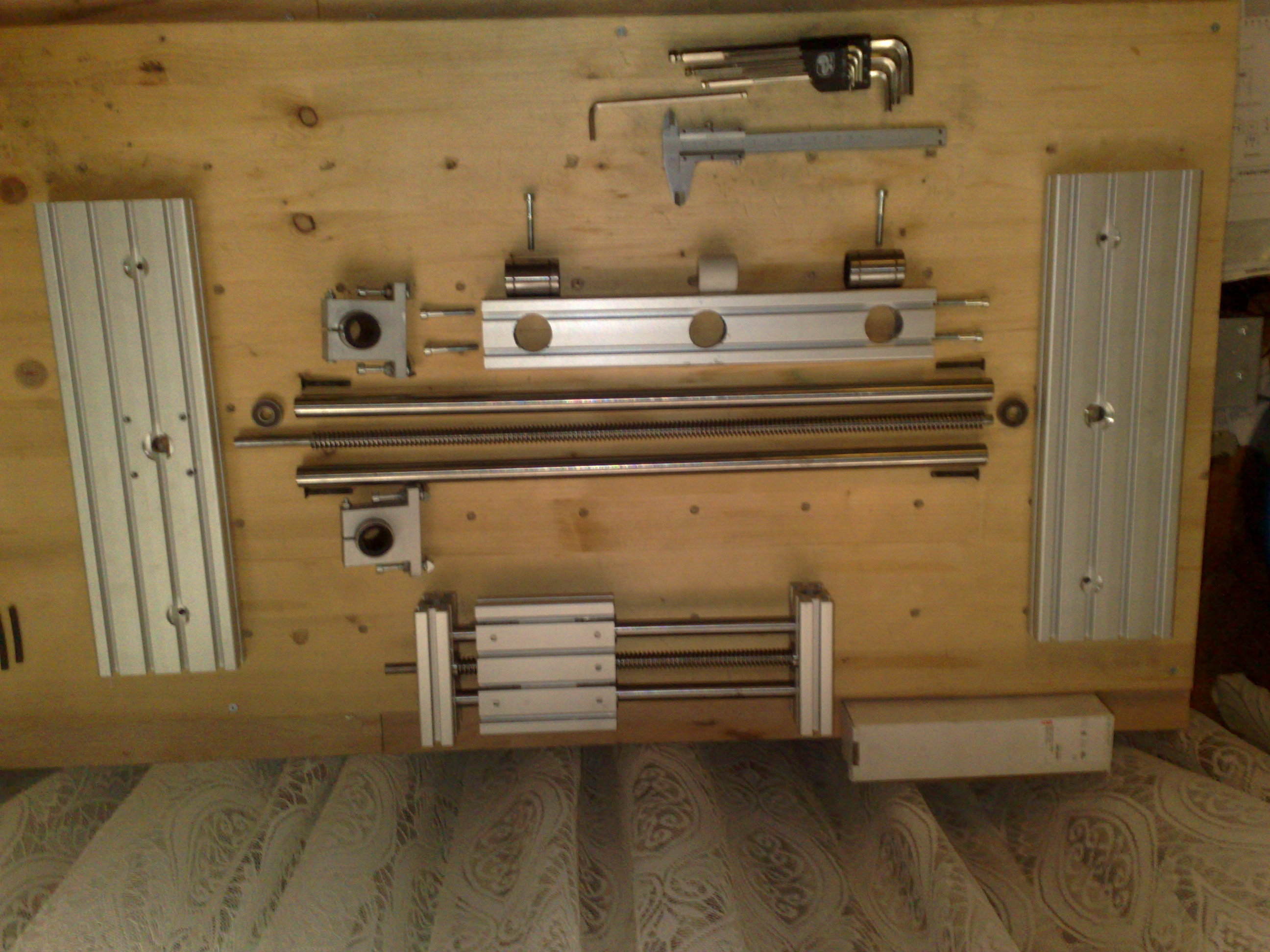
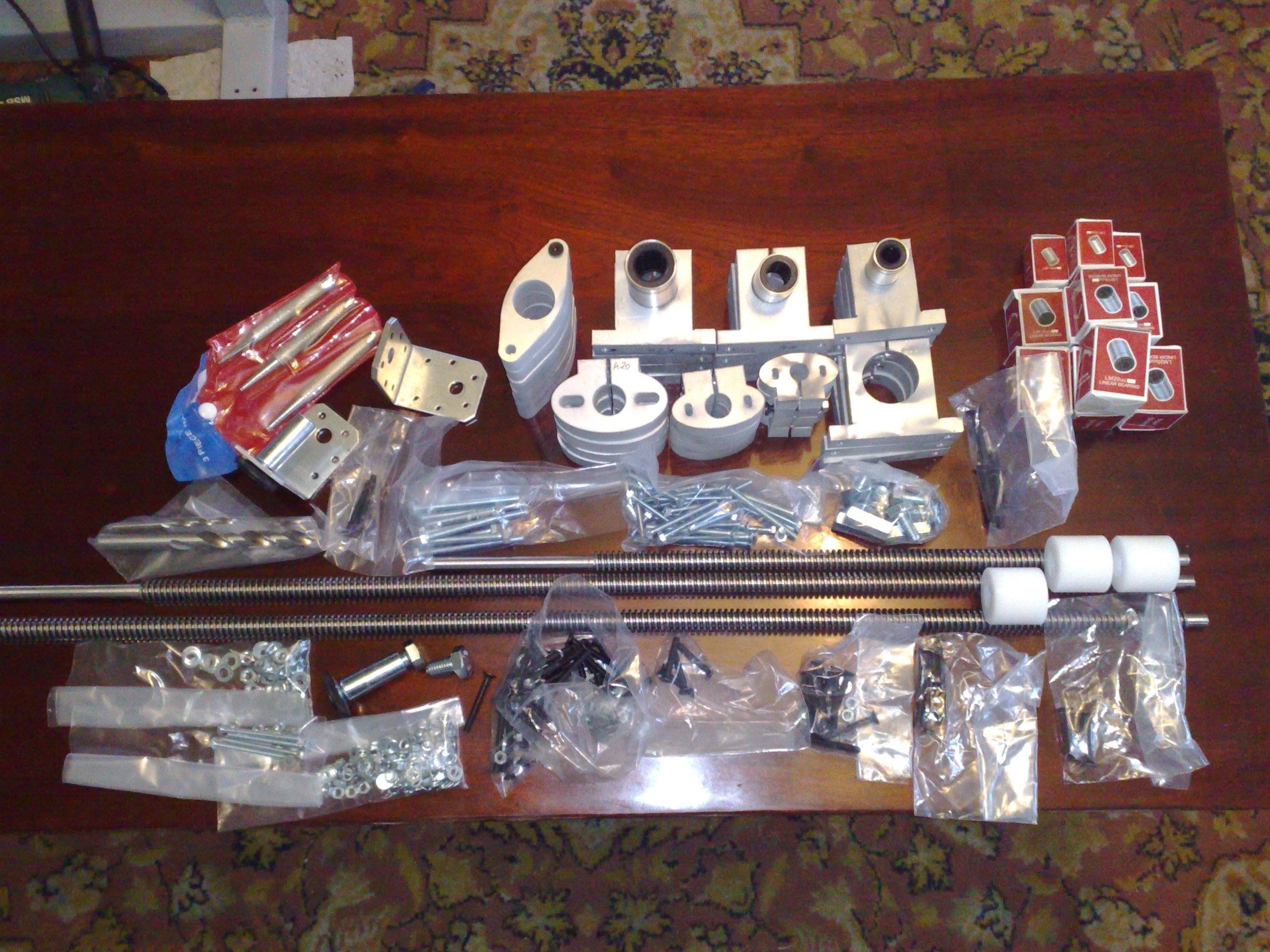
The mini CNC router is simple to build. If you have all the materials and parts prepared you should have it ready to work in less than 5 days.
I needed to build this mini CNC machine so I can make faster and more precise parts that I need for my other home projects.
You can also find the complete instructions at http://www.instructables.com/id/Mini-CNC… until I complete it here.
Project Steps
Mini CNC specifications
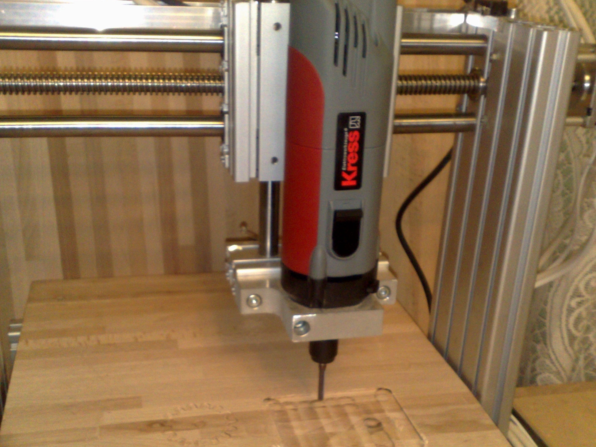
The working area of the machine is X=450mm (approx. 17.5 inch) and Y=250mm (approx. 10 inch) and it can mill parts as high as Z=110mm (approx 5 inch). The maximum milling speed on X an Y axis is 2400mm/min. and on Z axis is 1800mm/min. The resolution of each axis is 1/50 or two hundredths of a millimeter and one motor revolution on each axis results in 4 mm of movement. The router used is a Kress 1050. The number of parts used for building this mini CNC machine is 42, excepting screws and nuts, and the total cost is $1200.19.
Required tools and skills
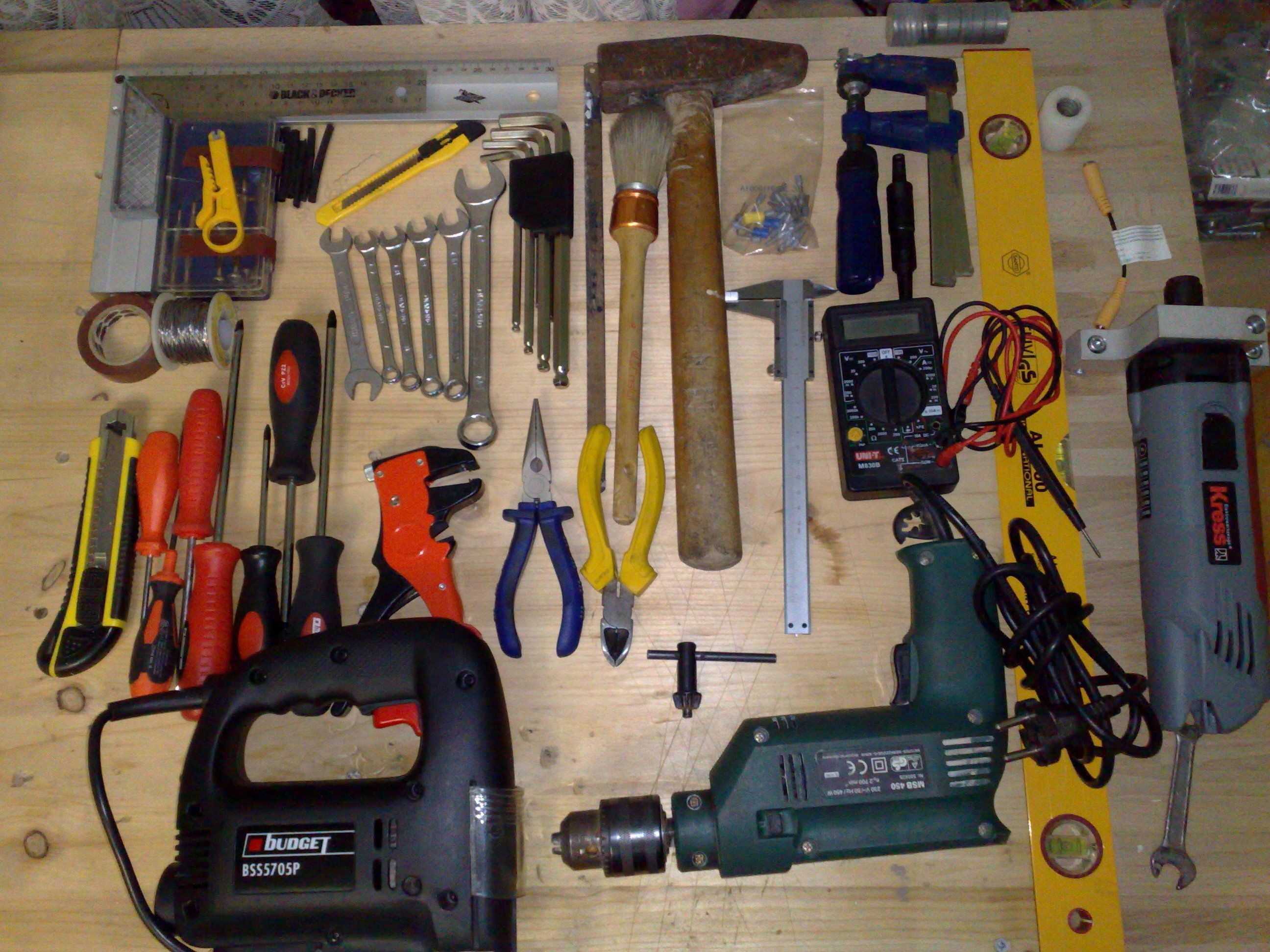
For this project you will need to have a set of screwdrivers and a set of hex keys or Allen keys, a drill for some extra holes, metal-cutting saw to cut some custom parts, soldering station or soldering gun to join the wires so they’ll have good conductivity, and a multimeter. You should have knowledge of basic electronics, how to solder and how to use a multimeter.
Ordering components
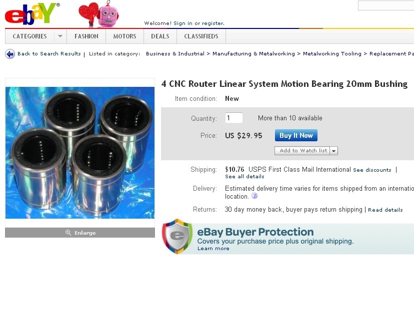
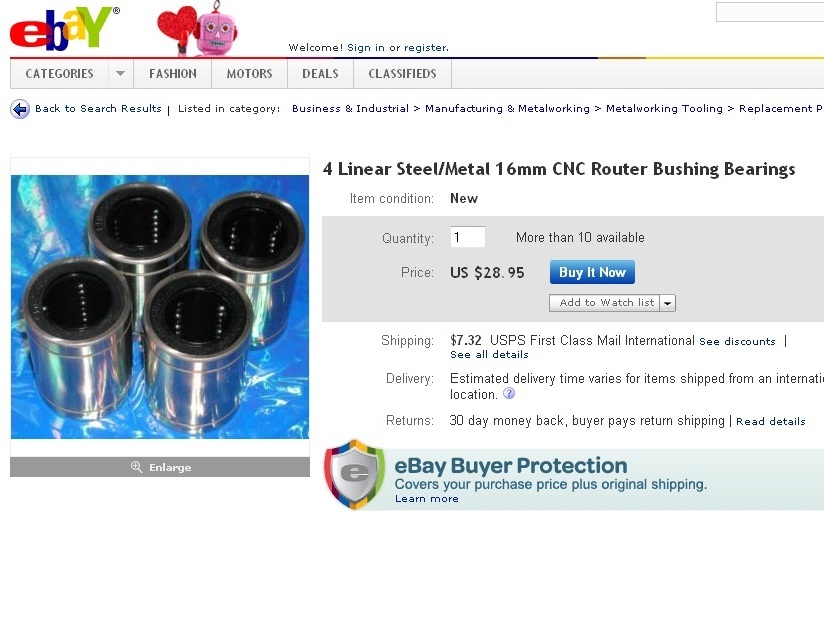
All the parts used to build the machine were bought from local dealers, so I suggest you do the same if it’s cheaper (parts + transport). If not you can find all the parts on eBay. The trapezoidal cylindrical nut was made in a local workshop.
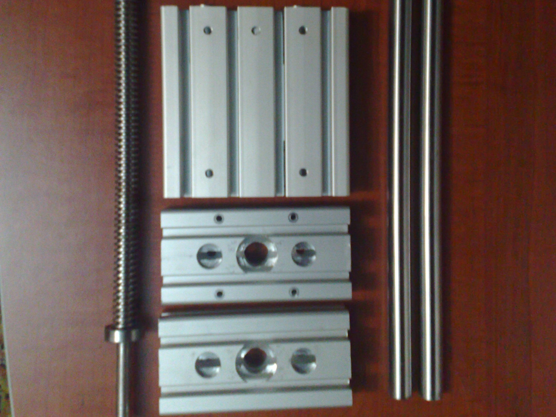
Mechanical components - aluminum profiles
The frame is made of aluminum profiles and the parts are:
X base parts – 2 pieces of 400x120x30mm (cost: $52.32);
Y frame parts – 2 pieces of 400x120x30mm (cost: $52.32), 1 piece of 380x60x30mm (cost: $13.16);
Y carriage – 1 piece of 120x120x30mm (cost: $7.85);
Z carriage – 1 piece of 120x120x30mm (cost: $7.85);
Z frame parts – 2 pieces of 120x60x30mm (cost: $8.30);
Machining the aluminum profiles (cost: $72.00). Total cost: $213.80.
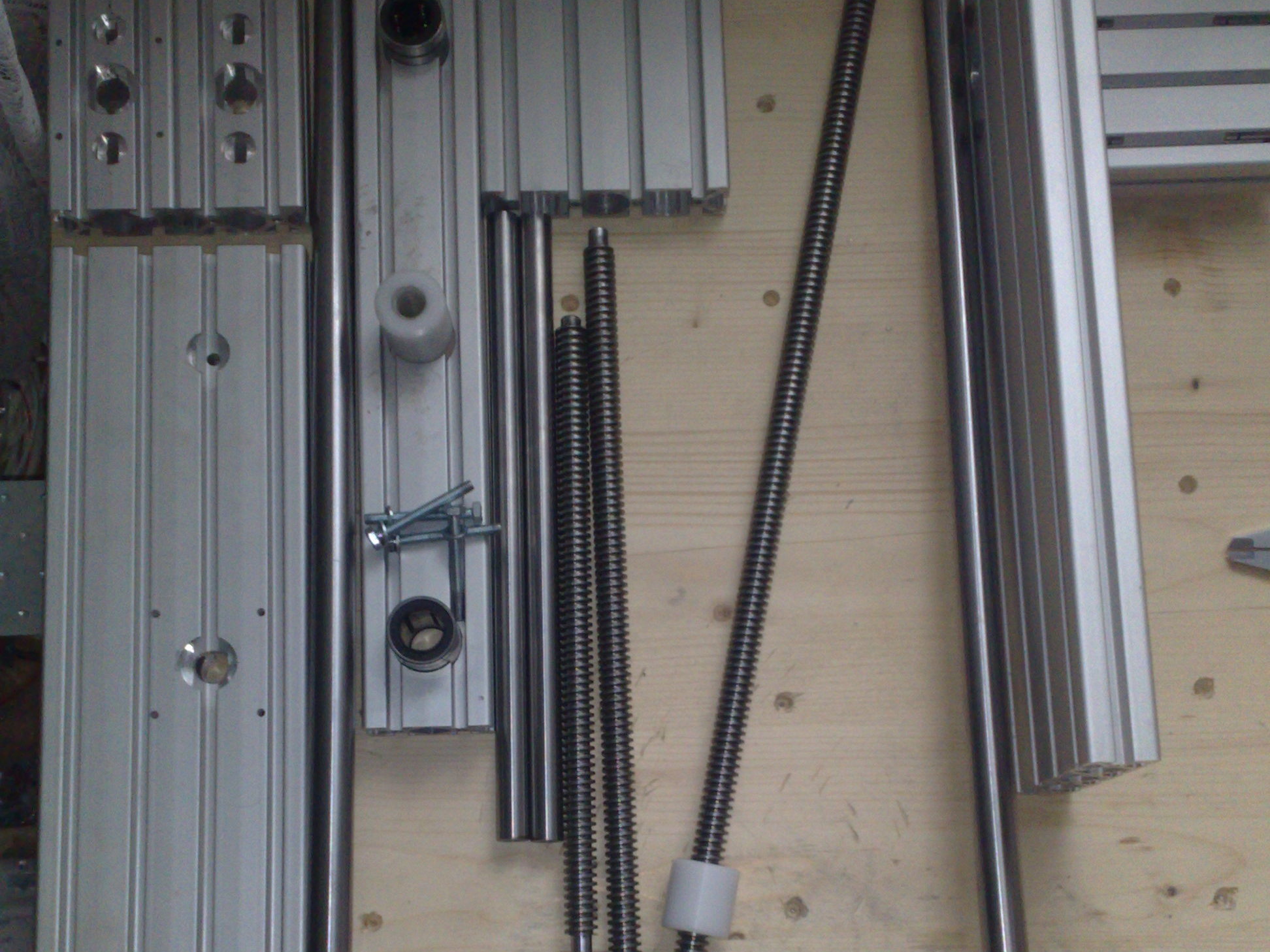
Mechanical components - shafts, bearings and leadscrews
Ø20mm precision steel shafts for X axis (cut from 1 piece of 60-inch=1524mm shaft): 2 pieces, each 600mm long (cost: $54.00);
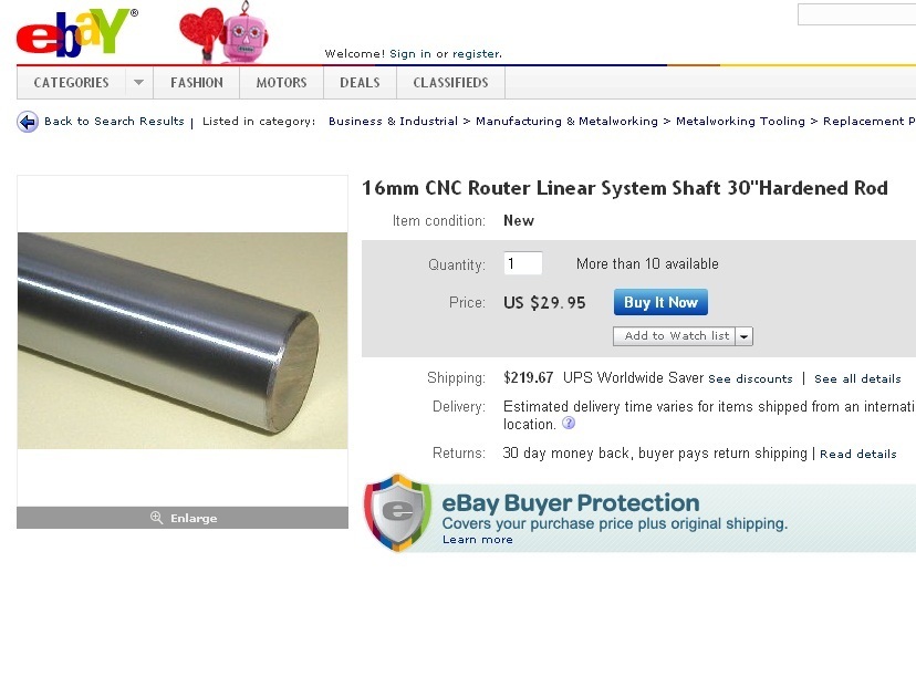
Ø16mm precision steel shafts for Y axis (cut from 2 pieces of 30-inch=762mm shaft): 2 pieces, each 390mm long (cost: $29.95);
Ø16mm precision steel shafts for Z axis (cut from 2 pieces of 372mm shaft left over from the Y-axis shafts): 2 pieces, each 300mm long (cost: $29.95);
Machining the precision steel shafts: 6 pieces (cost: $25.00).
Electronic components - Motors
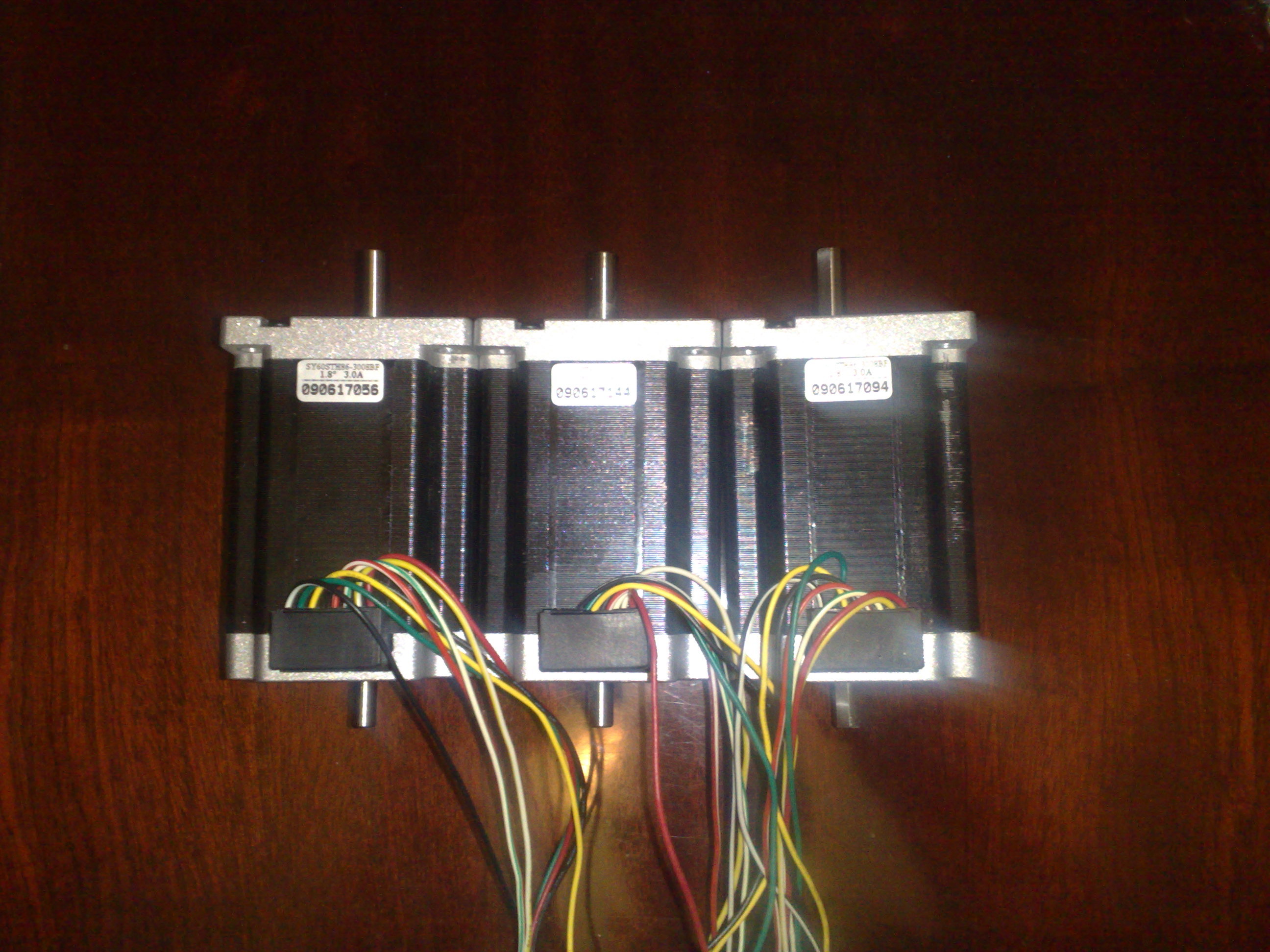
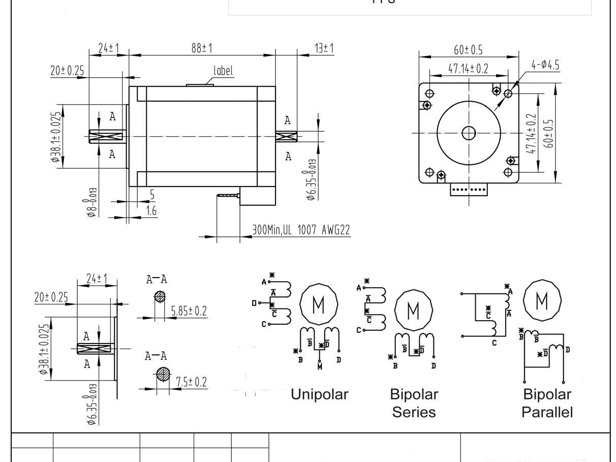
The motors chosen for this project are 3Nm 8-wire stepper motors that can be wired as unipolar or bipolar, depending on the user’s choice or which driver you have. Three 3Nm stepper motors (cost: $158.20).
A unipolar stepper motor has two windings per phase, one for each direction of magnetic field. This motor has only five leads. Bipolar motors have a single winding per phase. The current in a winding needs to be reversed in order to reverse a magnetic pole. There are two leads per phase; none are common.
Electronic components - motor controller
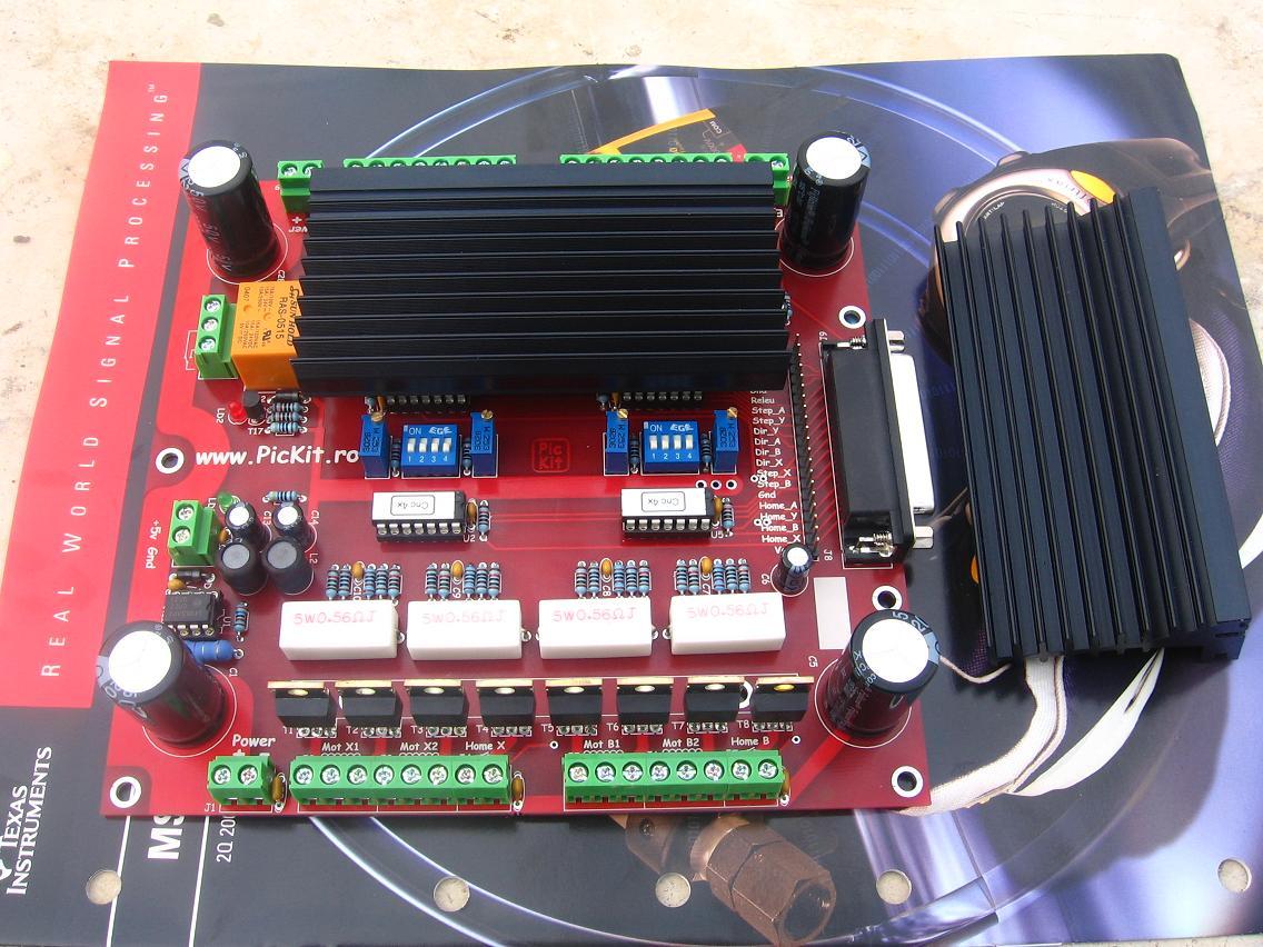
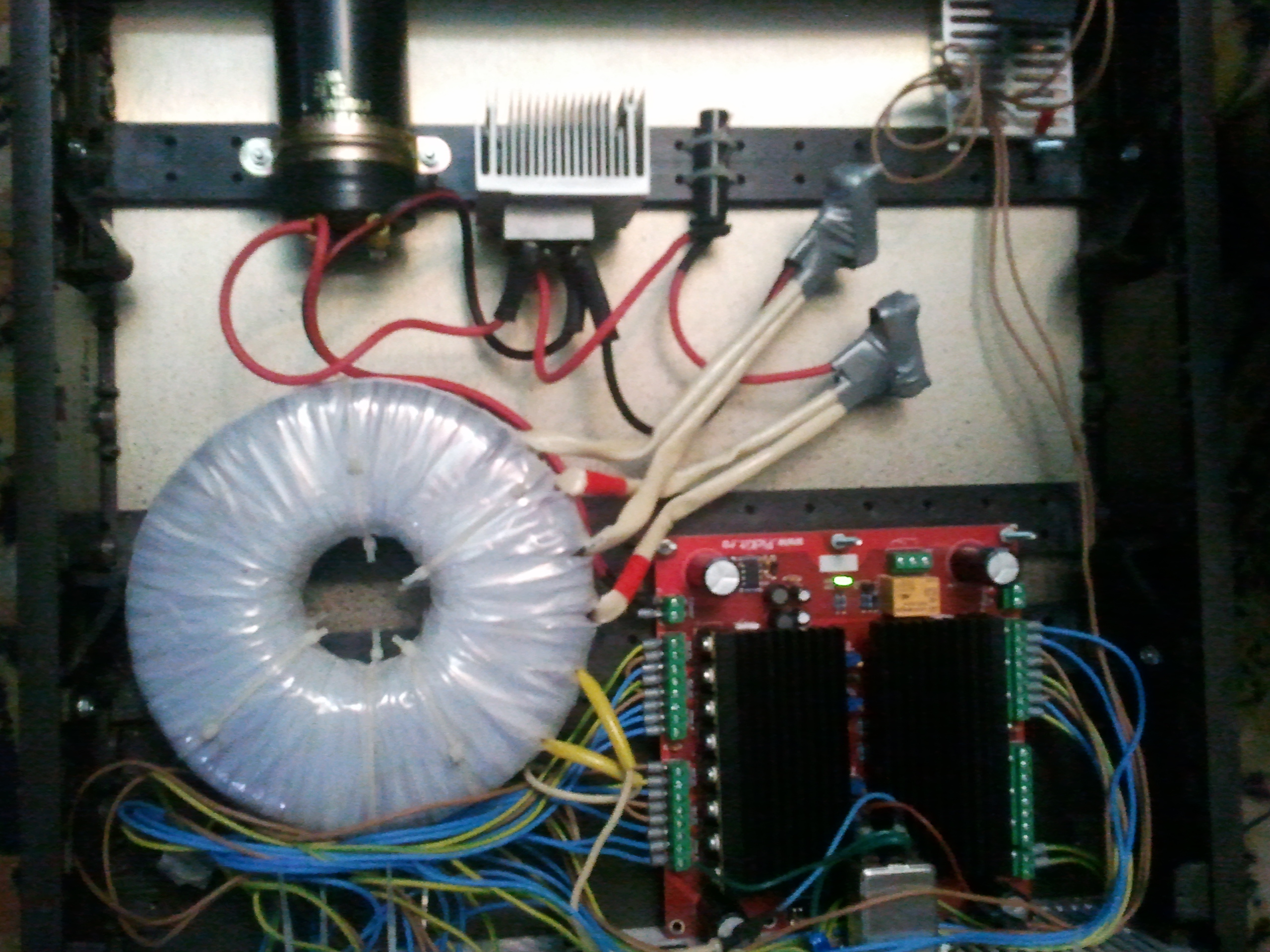
The stepper motor driver used is a unipolar 4-axis driver for 5A/phase motors. Cost: $82.50.
Electrical properties:
Input Power: 20-40V DC.
Stepper motor drive current: 1.5A – 5A/phase.
Compatible stepper motors: 2 or 4 phase, 6 or 8 lead stepper motors, 5A max.
Dimensions: 18 x 12 x 6 cm (L x W x H).
This board allows you to control 4 stepper motors, as well as receive input from two limit switches per motor and from an emergency-stop button, and it has a relay interface for spindle motors.
Power supply components
The power source contains one 600W toroidal transformer (cost: $76.60), one 50-amp rectifying bridge (cost: $1.90) and one 20,000µF capacitor (cost: $7.99). Total cost: $86.49.
Motor controller case
For the motor controller case I used an old Keithley236 source measure unit. I have removed all the guts of the old thing to make way for the new motor controller and power supply.