YouTube player

This project is based on work by MAKE magazine contributor Tom Zimmerman. Tom, who was honored in 2009 as California’s Volunteer of the Year for his unpaid teaching campaign in public schools, developed the idea as a hands-on activity to accompany his talks about the Mars rover program. Basically, he mounted an X10 wireless surveillance camera on a small R/C car frame, fixed some magnets to the front bumper, and challenged students to drive the vehicle around remotely and pick up scattered tin cans with the magnets.

That project was published as “Mini Mars Rover” in MAKE Volume 06, back in 2006. The X10 XCAM2 wireless video camera specified in Tom’s original build was one of the first small, inexpensive CMO-based 2.4 GHz wireless surveillance cameras marketed for home use. It has a maximum resolution of 510×492, and no onboard battery. Students who play with the project, Tom says, “soon find out that driving is a lot harder when their field of vision is as narrow as a video camera’s.” At the end of his article, Tom suggests several improvements for the ROV, including making your own battery pack (to save on the expense of buying a commercial one), adding a second camera (for back-up or front-bumper views), and adding onboard lights (for nighttime or low-light conditions).

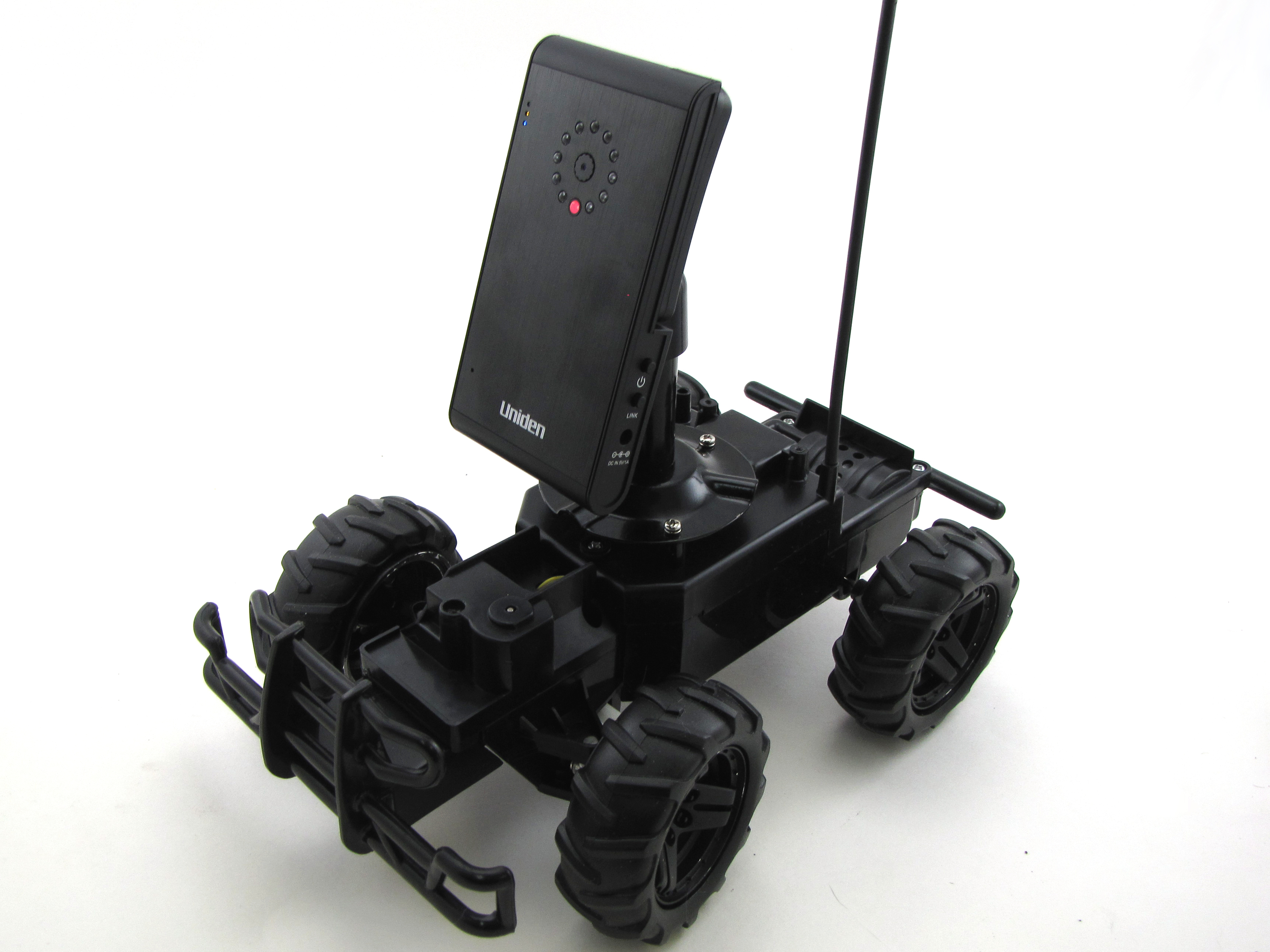
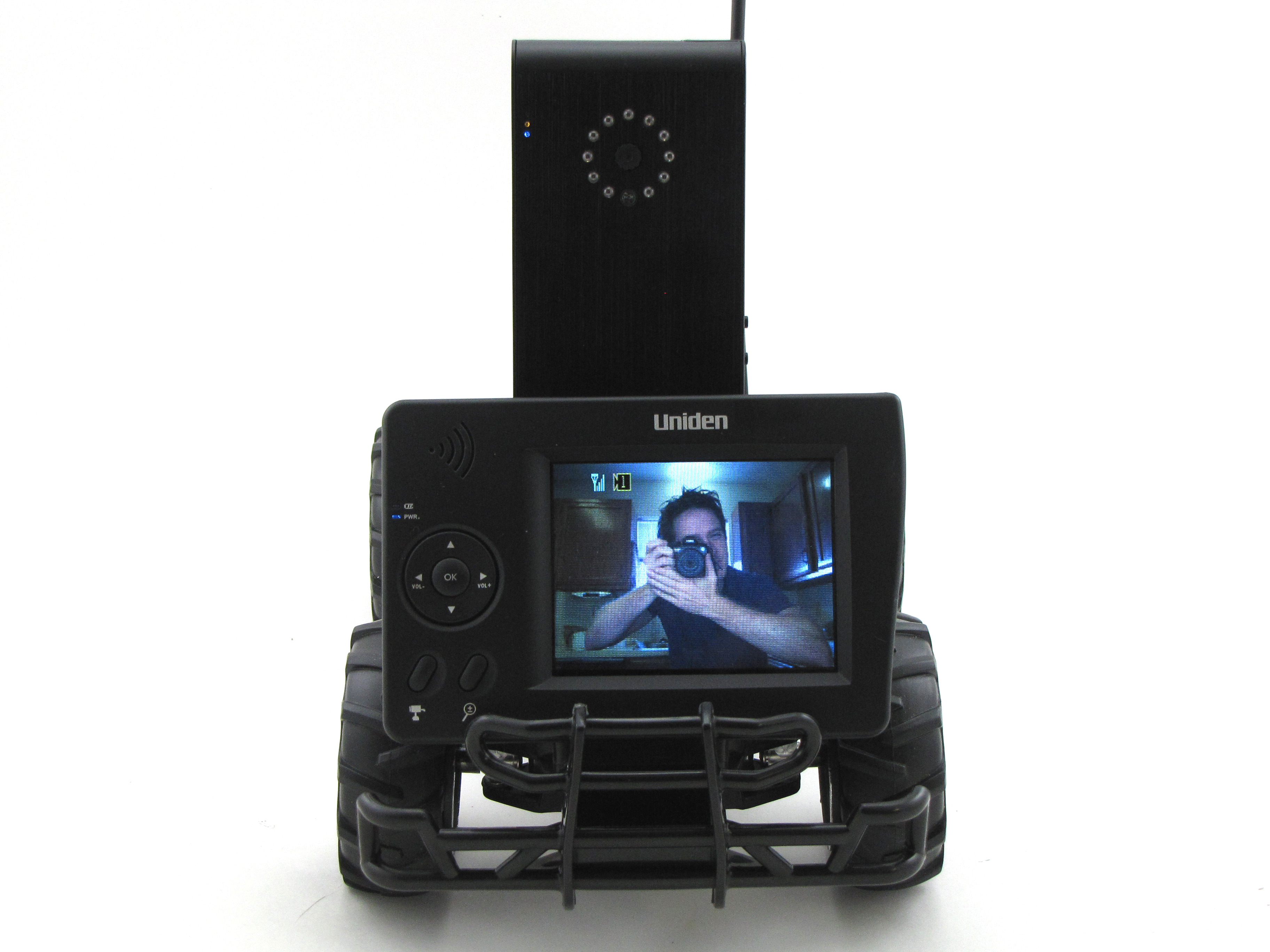
Wireless video technology has come a long way since 2006, and we felt like it was time for a reboot. After shopping around, we homed in on Uniden’s UDW10003 wireless surveillance system, which consists of a small handheld receiver unit and a bundled UDWC23 wireless camera. This camera sports VGA resolution of 640×480, onboard audio as well as video, an integral lithium-polymer rechargeable battery, and a “night vision” mode with a built-in solid state IR illuminator that automatically kicks in under low-light conditions.

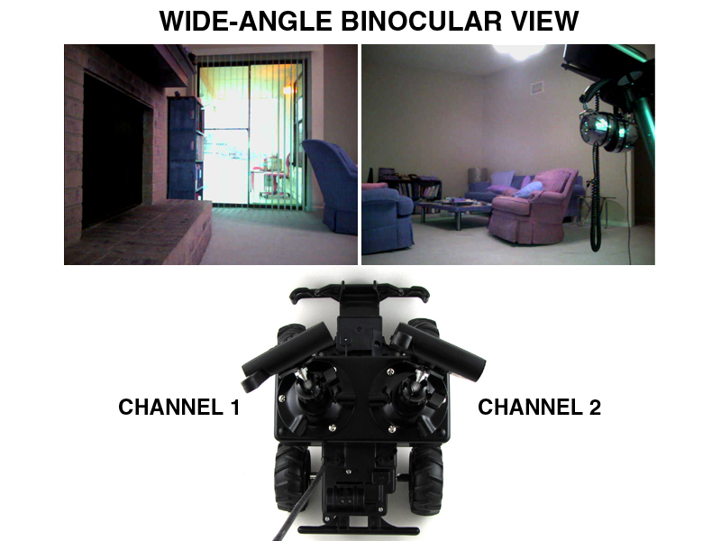
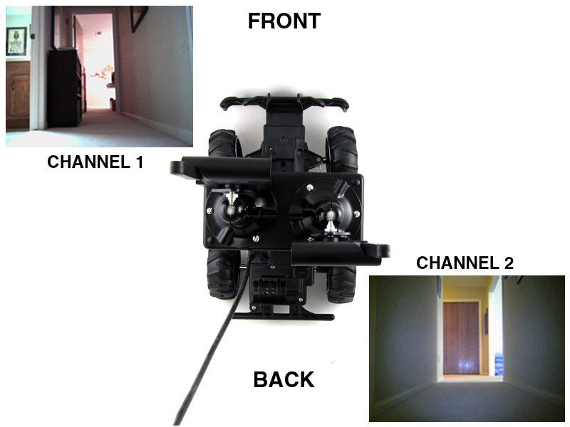
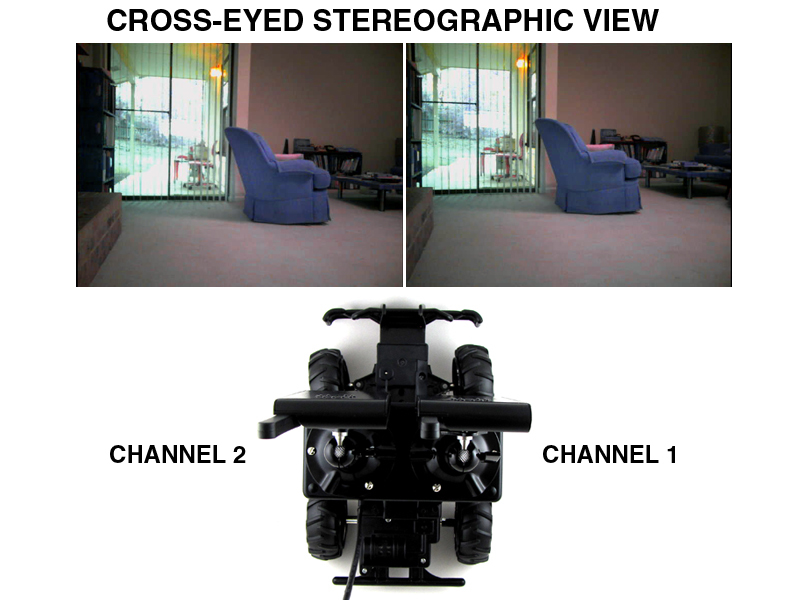
The receiver can handle up to four cameras simultaneously, and includes an RCA A/V out for direct connection to a display unit, and a USB port for serial communication with a computer. It can cycle between active cameras on command, or on a timer, and includes a “quad view” mode that arranges all four channel feeds on the screen at once. Besides the switchable front and back views suggested in Tom’s article, this simultaneous side-by-side viewing mode opens up some interesting new multiple-camera possibilities, including stereoscopic 3D!

Project Steps

Strip down the car.

We’re using Scientific Toys’ EZTEC-branded 1:17 scale Chevy Silverado R/C car as a camera platform. This toy is cheap, hacker-friendly, and works astoundingly well for the price.

First, detach the truck body shell from the chassis by removing 3 screws: 2 on top, in the truck bed, and 1 from below, between the front wheels.

Now, open the electronics compartment by removing 4 screws, as shown, and lifting the plastic cover gently up and off. The floppy wire antenna, which is threaded through a hole in the cover, should slip out the bottom as you do this.

Install the chassis standoffs.

Position the video camera mounting base on the car’s electronics compartment cover, as shown. Use the base as a template to drill 3 matching 5/32″-diameter holes in the electronics compartment cover.

TIP: You may find it easier to operate the drill through the baseplate if you remove the camera mount ball joint at the top of the stem first. Simply turn the wingscrew all the way out and the whole assembly will come off.

Turn the electronics compartment cover over, and attach three 10cm standoffs on the top side of the compartment cover using the screws that come with the standoffs.

Route the antenna back through the port in the electronics compartment cover, then reattach the cover to the car chassis using the original screws.

Prep the chassis.

Thread the floppy antenna through the plastic guide tube bundled with the car. Slot the tube into the antenna port to keep the antenna aerial in upright.

If you want to make cosmetic modifications to the chassis, now is a good time. I didn’t like the bare plastic color of the antenna aerial tube, so I covered it in black heat-shrink tubing. I also painted the wheel hubs flat black to cover up the shiny chrome.

Install batteries in the car and the controller. Though they’re more expensive, I like to use NiMH rechargables for R/C applications because they usually have greater capacity than alkaline cells, and are more environmentally friendly.

Turn on the car, grab the controller, and try it out! Note that the controller uses no power when it isn’t transmitting, so it has no on/off switch.

Mount one camera.

Secure the camera mounting base to the 3 standoffs on the car chassis using the standoffs’ bundled screws. These are nice because they have built-in lock washers to keep things from loosening up due to vibration.

Mount the camera to the base, as specified in the camera directions. Turn on the camera and turn on the base unit. If the camera and base unit are charged, you should see the video feed right away.

If you don’t see the video straightaway, plug the camera and/or the base unit into mains power, using their bundled adapters, and try again. If you still can’t see the feed, follow the manual directions for “pairing” the camera and the receiver.

Build the dual camera platform.

To mount a second camera, we need to widen the chassis a bit. We’ll use a simple black plastic project enclosure, which will allow us to mount everything neatly and provides a handy “payload” space for other equipment.

Demount the camera from the ROV, and then remove the mounting base. Use the mounting baseplate as a template, as before, to drill a triangle of 5/32″-diameter holes in the center of the enclosure lid, as shown.

Mount the lid, lip up, to the chassis hardpoints, using the screws bundled with the standoffs.

Now, arrange the 2 camera bases as far apart as you can on top of the enclosure box, as shown, and use them again as templates to drill six 5/32″ holes in the plastic. Set the mounts aside, and step-drill these holes up to 5/16″.

Install the dual camera platform.

Fit a rubber grommet into each of the 6 holes in the top of the project box. These will reduce strain on the mounting platform when the ROV is bouncing around in motion, and prevent the mounting nuts and washers from vibrating loose.

Align the camera mounting bases over the grommet-protected holes and pass a 6-32 x 3/4″ machine screw through each. Secure each screw inside the box with a flat washer and a hex nut, and tighten down securely. Don’t be afraid to crank down on the grommets a bit — that’s why they’re there!

Fit the project box top, with mounted camera bases, over its lid, which you secured to the R/C car chassis in the previous step. Use the screws bundled with the project box, and tighten them down with a Phillip’s head screwdriver.

Use 2 cameras at once.

Install the cameras on their mounting bases, power them up, and pair them with the receiver per their instruction manuals. There are several interesting ways to use a pair of cameras, and which you choose will affect both how the cameras are aligned on the car frame, and which camera is assigned to which radio channel. See below for details.

Wide-angle binocular vision. Angle right and left cameras out to each side by about 30°. The left camera should be assigned Channel 1, and the right camera Channel 2. View them side-by-side by setting the receiver to “Quad” mode. Together, the 2 cameras provide a much more natural 120° field of view.

Back-up camera. Point the left-side camera forward and the right-side camera to the rear. Alternate between them, as necessary (e.g. when reversing the car), by cycling between the 2 channels on the receiver. It doesn’t really matter which camera goes on which channel in this mode.

Stereoscopic 3D. Set both cameras facing forward at the same angle and elevation. If you know how to view stereograms, you can set the receiver to “Quad” mode and view the video feeds either as parallel or cross-eye stereo video, for a full 3D roving experience!

Conclusion

This is a system with lots of hacking potential. Of the mods and improvements Tom suggests in his original article, the only one we haven't achieved in this build is the addition of an ultrasonic rangefinder, which Tom describes as "way advanced." But note that Parallax now makes a handy all-in-one ultrasonic range sensor that would fit nicely on the front of the Mini Rover's camera box, with plenty of room inside that box for whatever electronics it needs. As for operator feedback, Tom suggests an audible "ping" sound that gets higher as you get closer to an object, and reports back through the camera's on-board microphone.

Demounted from the ROV, these wireless video cameras are pretty fun toys in and of themselves, and would be an easy way to experiment with XKCD-style "giant head" depth perception enhancement.

What would *you* do with it? Please let us know in the comments below!