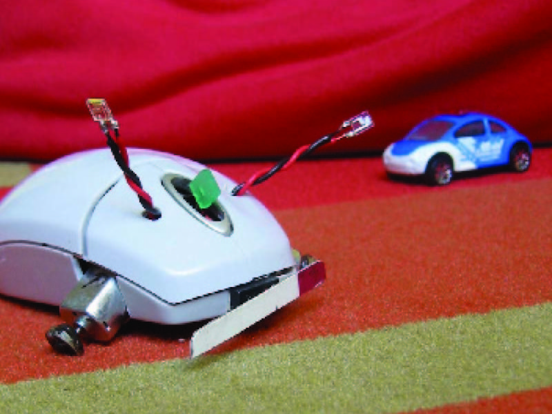
This project turns an analog computer mouse into a robot that’ll delight your friends and wow your workmates down on the cube farm. Mousey’s behavior is fittingly mouselike. It scoots very quickly across the floor, thanks to lively little DC motors. And when the critter crashes into anything, it backs away and speeds off in another direction.

The robot’s “brains” use an ingenious hack based on an audio operational amplifier (or “op amp”), an 8-pin chip that’s normally used to drive answering machine speakers and other lo-fi audio equipment. Following the circuit designer Randy Sargent’s original design, Mousey uses this chip to boost two light-sensor inputs to motor-powerable levels. The result is a simple, fast-reacting analog circuit that fits (tightly) inside of a computer mouse case.

Project Steps

Plan your build.

Mousey uses freeform soldering, meaning we’ll solder the parts without a printed circuit board (PCB), building everything right inside the mouse case.

We’ll begin by prepping the case and installing the motors, then breadboard the circuitry to make sure everything works.

Determine if the mouse has enough space inside. Unscrew the mouse case and eyeball it, making sure that it’ll hold the two motors and a 9v battery.

Screws may be hiding under little nylon feet or tape strips on the bottom. Save these bits so you can put them back at the end of the build; they’ll help reduce friction.

Perform a mouse autopsy.

Remove all of the mechanics and electronics from inside the mouse. Unhook the mouse cable from its plug-type connector, pop out the scroll wheel (if it has one), and pry out the PCB.

Use a Dremel or other rotary tool with a cut-off wheel or grinding head to remove everything from the inside of the mouse case (except the screw post that attaches the bottom of the case to the top).

Plastic dust is nasty stuff, so work on newspaper and wear safety goggles and a dust mask.

Add the power switch.

The last piece of prep work is adding the power switch, a large toggle placed rear topside so it looks like a tail. Find an appropriate mousey-tail location, then drill a hole in the case big enough for the switch.

If the switch has a threaded bushing and two nuts, take one nut off, insert the bushing through the hole, and then tighten the nut back down onto the outside of the case.

In some cases, a plastic screw post interferes with the tail. If so, cut out the post and reconnect the top and bottom halves with tape or glue.

If you want to create a more critter-like look for your Mousey, you can add a length of plastic tubing or other material over the toggle to create a tail.

Figure motor and battery placement.

Figure the arrangement of the bigger components and cut openings for the motors. Mouse shapes vary, so use your judgment here.

The two motors should be perpendicular to the centerline of the body. Leave enough space behind the motors for the battery.

Once you’ve placed motors and battery, cut openings for axles and wheels (the drive shafts and gears of the motors). The shaft angles coming from the body should support the bot and set the proper speed. The steeper the angle, the less rubber meets the road − but this is good, as Mousey can move too fast. 60 degrees is about right.

Installing the bump switch and adding tires.

Your mousebot will have one giant “whisker,” a bump switch (courtesy of one of the mouse’s button switches) that triggers the bot’s scuttleaway behavior.

Look on the mouse PCB for a tiny plastic box that clicks when you press it down. Desolder it.

With switch removed, test-attach it with poster putty to one side (or the center) of your mouse’s front end. Tape a long strip of hard plastic in place, so that it covers the tiny switch button and runs along the front of the mouse like a wide bumper. When you press the plastic, you should hear an itty-bitty click.

Once you’re happy with the placement and operation of your bumper, drill a small opening in the mouse case bottom for the switch to stick out (in the image here, the switch is in the center of the front). Your plastic strip should be about ¼” x 2½”.

Now you can add some tires to your motor drive shafts. Find a rubber band with the same width as the sprockets on the drive shafts (if your motors have sprockets on them). Cut to length, wrap, and glue the rubber band onto the shaft. You can make the wheels thicker by continuing to wrap the band. Rubber or plastic tubing make good tires, too, as does corrugated tubing from a Lego Mindstorms kit.

Understand Mousey's brain.

The LM386 op-amp, the main component of Mousey’s control circuit, “listens” to two input signals. If one signal is lower than the other, the chip boosts that signal to equalize the one output. In our case, the inputs are light values rather than audio.

If we hook this output to two DC motors, we have a little brain that reads input from two light sensors, compares them, and boosts the power on the dimmer side. This creates a robot that follows a light source, auto-correcting itself as it moves.

The bump switch triggers a relay that reverses the two motors’ inputs for a few seconds. This makes Mousey scuttle away from light after any collision, adding to its lifelike behavior.

There is a slight correction in the circuit diagram here (the connections for the LED and 1K resistor) over the original project in MAKE Volume 02. The mouse works either way, this arrangement just improves sensitivity of the IR sensors. The breadboard images (Steps 9-11) DO NOT yet reflect this fix, so make sure to follow the circuit diagram when installing these two parts.

Create Mousey's eyes.

For Mousey’s eyes, we can use the mouse’s own two IR emitters, a.k.a. phototransistors. During normal computer mousing, these shine infrared through the mouse’s perforated encoder wheels, which is then received by photodetectors on the other side.

These emitters can work as both transmitters and receivers. On most mice, the emitters are clear plastic boxes with a tiny dome protruding from one face, while the photodetectors are solid black. We want the clear emitters.

Find the clear emitters and desolder them from the PCB. You are now the proud owner of a pair of robot eyeballs!

Give Mousey eyestalks.

Our IR emitters only have two stubby little pins on them. We need to give Mousey some optic nerves − eyestalks that jut from the front of its body. These will allow you to adjust Mousey’s sensitivity to light by bending the stalks around.

We need to determine which pin is positive and which is negative. Set your DMM to Diode Check, and touch the probes to each pin. If the read-out is “OL” (no connection), reverse the probes. When connected correctly, you should get a reading of about 1V, with the red probe indicating the anode (or positive) pin.

If your DMM doesn’t have Diode Check, look for a positive voltage of about 0.6V when the red probe is on the anode.

To create the stalks, cut four 6½” pieces of 22-gauge, solid-core hook-up wire. If you have red and black, cut two of each color. Solid core is better than stranded in this case, because it makes stiffer stalks.

Solder the red wire to the cathode (-) pins on the emitters and the black wire to the anode (+) pins.

The colors are switched because we’re “reverse-biasing” the diodes; with current flowing in the normal direction, additional electrons excited by light in the diode’s junction get lost in the flow, but with current trickling in the opposite direction, the difference is more noticeable, making the circuit more sensitive.

When the wires are soldered in place, twist them together and strip some of the jacket off of the other ends.

Install the op-amp chip and main control circuit.

Install the LM386 chip across the trench on your breadboard.

With all ICs, pins are numbered counter-clockwise around, starting at the little dimple.

Connect tie-points for Pins 1 and 8 together with a piece of hook-up wire. These pins control the op-amp’s gain; by connecting them with a jumper, we’re increasing the circuit’s sensitivity to input.

Connect the eyestalks by taking the black wires from each and connecting them to tie points for Pins 2 and 3 (the op-amp’s inputs). Connect the red wires together by plugging them into a node about five or six rows left of the chip.

Our horizontally-oriented board is organized with +/- power supply at top/bottom and all chips facing left. Translate accordingly for different breadboard layouts.

Plug the negative lead of an LED (the shorter end) into the node with the two red eyestalk wires, and the positive lead into a new node on the opposite side of the trench. Then take a 1k-ohm resistor and plug one end into the LED’s positive node, and the other into the positive/upper power bus.

Connect the power pin of the LM386 (Pin 6) to the positive power bus, and ground (Pin 4) to the lower/negative bus. We’ll connect the battery later.

To create the runaway circuit, we need the bump switch you already pulled, a 5V DPDT relay, a transistor, and a simple timer made of a capacitor and resistor. When the switch is triggered, the transistor enables the runaway circuit, with the capacitor powering Mousey’s motors in reverse. When the capacitor has discharged, the transistor switches motor control back to the light-following circuit.

The resistance and capacitance determine the rate and amount of current discharged. You can play with different values until you find the runaway behavior you want. Try resistors in the 1k- to 20k-ohm range, and cap in the 10- to 100-microfarad range. The higher the value, the longer the discharge time.

We used a 10k-ohm resistor and a 100-microfarad capacitor, which gave about 8 seconds of fast backing up.

The relay’s pins are spaced apart widely, so we’ll refer to pins by their breadboard locations.

Plug in the relay about six nodes to the right of the LM386, or 1-16 (although the relay actually has only eight pins).

Cross a wire from Pin 8 to Pin 11 and another from Pin 6 to Pin 9. These wires will reverse the motor connections when the relay is engaged.

Plug the cap’s (+) lead into an unused row just left of the relay, and the cathode to the negative power bus. On electrolytic caps, the cathode is usually marked with a stripe.

Plug in one end of the higher-ohm resistor to connect with the capacitor anode, and jump the other end over the trench to a new node on the other side.

Spread the transistor’s pins and plug it in with the flat side facing the trench, above the relay, such that the center pin (base) connects to the resistor lead, the left pin (emitter) is in an unused node, and the right pin (collector) connects to Pin 16 of the relay.

Plug one hook-up wire into the bottom resistor and capacitor node, somewhere between the two, and a second wire up to the positive power bus. Bend the tips of the wires so they can touch, but keep them separated. These wires will act as the bump switch when you touch them together.

Run two wires to connect Pin 1 and Pin 8 on the relay with the top/positive power bus. Connect Pin 9 to the negative bus. Finally, connect the transistor’s left pin (emitter) to the bottom/ negative bus. This connects the relay and transistor to power.That’s it — look over your cool robot brain!

Freeform Mousey's control circuit.

Now that we have a light-hungry robot brain, we need to install it in our mouse body so that it can feed (cue Night of the Living Dead sound effects). In general, we’ll want to use a lighter wire, such as stranded 22-gauge, to tuck into the case and put less stress on the solder joints.

Before soldering, test fit the parts, starting with the battery, motors, and bump switch. Position the other components around these. The resistor/LED sensitivity-booster circuit will fit against the top half. As you arrange, check that the case still closes. When you’re happy with your arrangement, empty the case and install the battery using two-way tape, Velcro tape, or poster putty. That way, you can replace it when Mousey gets that run-down feeling.

MAX HEADROOM! One of the biggest mistakes people make with Mousey is having too much wire inside the case so that the top won’t fit back on. Make sure all of your wires are as short as possible throughout the build and keep making sure the top fits!

Install the relay.

To prepare the relay, put it in “dead bug mode” (on its back), and solder short lengths of solid-core wire to the bottom four pins (the switch pins) in an X.

Solder the transistor’s collector (the right pin when you’re looking at the flat side with the pins pointing down) to the top-left coil pin on the relay (Pin 16 on the breadboard). Solder a 4″ piece of black wire (denoting negative) to the transistor’s emitter (left-most pin). This will connect to Pin 4 of the IC and power negative (ground).

Solder a short red wire connecting the top and bottom pins on the relay’s right side (Pins 1 and 8 on breadbaord). Solder a 2″ black (negative) wire onto the bottom-left pin (Pin 9 on BB), and then a 3″ red wire onto the bottom-right (Pin 8 on BB).

Affix the relay into the case, in dead bug mode. Allow it to dry (if gluing) before soldering anything else.

Using red wire, solder the left motor’s positive terminal to the second pin down on the right side (Pin 4 on BB), and solder the right motor’s positive to the opposite pin on the relay (Pin 13 on BB).

Connect the bump switch components.

With the relay close to the front, we can chain together the timer resistor, capacitor, and bump switch without needing additional wires. As with the relay, we’ll attach components “out of body” first, for easier soldering.

Solder 4″ black wire to the cap’s negative lead (which should be clearly marked — electrolytic capacitors are polarity-sensitive).

Using your multimeter on the 3-pin bump switch, determine which side pin connects with the middle pin when you click it, and clip off the other unneeded pin.

Solder the cap’s positive lead to the remaining side pin of the bump switch, and solder one end of the timer resistor to that same switch pin.

Solder a 2″ red lead to the middle switch pin, then glue the switch into the the body, through the hole you cut earlier.

Solder a lead between the transistor’s middle pin and the free end of the timer resistor.

Power the motors.

Solder two 2″ black wires to the motors’ negative terminals, then solder the stripped ends of these two wires together side-by-side.

Solder a third, 3″ black wire, to these joined ends, then solder it to the control chip’s output pin (Pin 5 on the IC).

Install the LM386 control chip.

Bend Pins 1 and 8 of the op-amp chip down and solder them together.

Find the black wires from the transistor, relay, and capacitor, strip the ends, and solder them all together side-by-side.

Solder the battery snap’s negative wire to this same junction.

Solder a 1″ black wire to Pin 4 of the op-amp, and the other end to the negative wire junction.

Solder the red wire from the relay to Pin 6 of the chip. Then glue the chip into the mouse case (in dead bug mode).

Install Mousey's eyes.

The buttons on most computer mice are separate, semi-attached pieces of plastic. To give Mousey’s eyes a solid foundation, glue the buttons down, wait until dry, then drill small holes in Mousey’s lid to thread the eyestalks through.

Thread about 1¾” of stalk through each hole. On the inside, trim the two red wires so that they just overlap against the underside of the lid. Solder them together. Run the black wires along the inside, to the back, and bend them down where the op-amp is located (don’t solder them yet).

Make the sensitivity booster circuit by cutting a 1″ piece of red wire, and soldering one end to the 1k-ohm resistor and the other to the LED’s anode.

Connect the booster by soldering the free end of the resistor to the middle pole of the toggle power switch and the LED cathode to the junction of the two red eyestalk wires.

Mark where the LED sits, gently bend it aside, and drill a hole in the case for it to poke out of (unless it can already come up through the scroll wheel slot). Push the LED through and hold it in place with tape.

It's all about connections.

We almost got bot! Now install the front whisker and make the final connections between power, the switch, and the control chip. There’s no photo of these final steps, because they happen inside a semi-closed mouse. But you’re such a circuit-hackin’ fool by now that you don’t need us anymore.

Solder the black eyestalk wires to Pins 2 and 3 on the LM386.

Solder the red battery wire to either of the side poles of the toggle switch.

Solder a red wire from the toggle’s center pole to Pin 6 of the IC, or to either Pin 1 or Pin 8 of the relay. Solder another red lead from the unconnected bump switch pin to one of these same locations

Cover all exposed leads and junctions with electrical tape to prevent shorts. Then glue or loosely tape your plastic “whisker” to the bumper switch, so that it clicks on impact.

Finally, snap in the battery, and screw or tape the two mouse halves back together. Then put Mousey on the floor, switch it on, and watch it go!

Mousey Games

If all went well, Mousey the Junkbot’s behavior will be apparent once you flip its tail. It should zoom away and eventually hone in on the brightest area in the room. It works best if you limit Mousey’s surroundings to just one bright source of illumination − one light or sun-soaked window. Below are some other fun experiments to try.

Put Mousey in the hallway and close all doors except one. Make the open room as bright as possible, and see if Mousey eventually scuttles in there. Try orienting Mousey in different starting positions.

Tune Mousey’s light sensitivity by bending the eyestalks. Move the stalks farther apart, closer together, and bend in different directions until you get the steering you’re looking for.

Use a flashlight to lure Mousey around. This drives pets insane! But be careful; agitated pets will attack Mousey and try to rip out its little robot heart.

Troubleshooting a wayward mousebot.

If you turn on Mousey and nothing happens (cue laughing clarinet, “Wha-wha-WHAAAA”), or if it acts strangely, turn it off immediately. Something went wrong with the build. Below are a few things to check.

First, ask yourself the tech-support alpha question: is it plugged in? Make sure that the battery is new, the snap is well-seated, and its positive and negative wires are properly connected. Then make sure that bare wires, pins, and solder joints are not making “unauthorized” contact with one another. One sign that you may have such a short circuit is if the battery gets warm.

Next, double-check all solder connections against the instructions. Besides being in the right places, they should all be fat, shiny, healthy-looking joins. Use the multimeter to check resistances, and resolder anything suspicious.

If Mousey frantically spins in a tight circle, you’ve probably hooked the motors up incorrectly. Reverse the wires that connect to the motor on the side that’s going backwards.

Conclusion

This project first appeared in MAKE Volume 02, page 96.

Related Posts on Make: Online:

Make Mousey the Junkbot: MAKE Video Podcast

http://blog.makezine.com/archive/2007/06...

Mousey the Junkbot Video

http://blog.makezine.com/archive/2005/05...